I think we are getting closer to Nirvana when we are speaking of good powersupply.
Whole Hi end end Audio boils down to how good power supply is Not the gold plated connectors and Oxygen free copper.
Transformers are best but those massive reservoir capacitors and Inherent resistance of coils leaves no choice but to look for exotic SMPS technologies.
Its been an year I am trying my hard luck with Sg3525 and Tlo494,I admit its no easy.Its rocket science,Black art,spiritual,Divine whatsoever to get a neat stable working SMPS.
Difficult part is the transformer yes someone said it. The core material is very tricky.Then comes High frequencies and Parasitic capacitance inductance and all of type of evils rolled up into one is called SMPS.
Last edited:
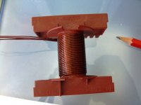
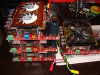
I didn't do much lately regarding this subject but I started dismantling some CRT TVs and monitors, from which I salvaged parts especially flyback transformer cores (those with two U halves and a metalic clamp) and generic E cores from their power supplies.
I also found this website which explains how to calculate a half bridge topology transformer
Tahmid's blog: Ferrite Transformer Turns Calculation for Offline SMPS Half-Bridge Converter
I also found this website which explains how to calculate a half bridge topology transformer
Tahmid's blog: Ferrite Transformer Turns Calculation for Offline SMPS Half-Bridge Converter
I think we are getting closer to Nirvana when we are speaking of good powersupply.
Difficult part is the transformer yes someone said it. The core material is very tricky.Then comes High frequencies and Parasitic capacitance inductance and all of type of evils rolled up into one is called SMPS.
I really believe using litz wire until 50 kHz it is a myth
We can calculate the skin effect and we would notice the use of normal 0,6 mm diameter wire is just enough.
For pretentious guys it can use silver plated wires.
Regards,
Mircea.
Attachments
I have just bought a 30m roll of 25mm wide ~1.6mil/thou thick, including adhesive, Kapton.
Is this suitable for the interlayer insulation film?
Is this suitable for the interlayer insulation film?
I have some experience with litz wire but like I said it is a myth until 50kHz.
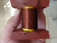
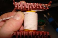
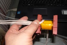
Kapton tape is just fine but you must pay attention between primary and secondary winding.
I used aluminium tape like un shield but of course, not in short circuit.
Primary winding split in two part.
Regards,
Mircea.
Kapton tape is just fine but you must pay attention between primary and secondary winding.
I used aluminium tape like un shield but of course, not in short circuit.
Primary winding split in two part.
Regards,
Mircea.
Attachments
AndrewT, Mylar tape is the typical insulating tape used in transformers. Kapton tape is a step up, higher temperature range and it costs more.
For a cheap solution clear packing tape is usually mylar.
For a cheap solution clear packing tape is usually mylar.
I really believe using litz wire until 50 kHz it is a myth
We can calculate the skin effect and we would notice the use of normal 0,6 mm diameter wire is just enough.
For pretentious guys it can use silver plated wires.
Regards,
Mircea.
Search for proximity effect, leakage inductance, and LLC converters!
Proximity effect can induce much higher eddy current in a wire than the current flowing in it normally. A wire in a coil is not only in the field generated by that piece of wire (like in the calculation of skin depth assumed), but the other turns also generate magnetic field which is added. This is not myth, nor only theory. You can heat up an air core coil made of 1 mm wire with only 0.5 A at 50 kHz. Strongly coupled trafos are less sensitive to this, leakage transformers are very sensitive.
Really?
You must to study more or perhaps I have some lack of knowledge.
I'm not talking about resonant mode.
Regards,
Mircea.
Attachments
Last edited:
Unfortunately I study enough.
My first SMPS was in resonant mod with Ncp1392 driver from ON semiconductors.
Sample of course.
My first SMPS was in resonant mod with Ncp1392 driver from ON semiconductors.
Sample of course.
I find that sellotape and similar and the brown packing tape are quite low temperature.AndrewT, Mylar tape is the typical insulating tape used in transformers. Kapton tape is a step up, higher temperature range and it costs more.
For a cheap solution clear packing tape is usually mylar.
I would not dare use them inside a transformer as interlayer insulation.
The chinese koptan (mispelling of Kapton?) is very cheap and should be of adequate temperature rating, so I asked. It's maybe a bit thin but hopefully will do the job.
Do a search for "mylar packing tape" it comes right up. Or polyester same thing different trade name.
3M #1298 mylar/polyester tape is very popular for transformers.
Electrical OEM : 3M? 1298 Polyester Film Electrical Tape, White, Flame-Retardant Acrylic Adhesive, 1 mil film, 1 in x 72 yd, (25,40 mm x 66 m), 36 per case
The film is 1 mil thick = .001" and with adhesive 2.5 mils = .0025"
Do you have a spec for your Kapton film without adhesive?
Electrical OEM : 3M? 1298 Polyester Film Electrical Tape, White, Flame-Retardant Acrylic Adhesive, 1 mil film, 1 in x 72 yd, (25,40 mm x 66 m), 36 per case
The film is 1 mil thick = .001" and with adhesive 2.5 mils = .0025"
Do you have a spec for your Kapton film without adhesive?
The chinese koptan (mispelling of Kapton?) is very cheap and should be of adequate temperature rating, so I asked. It's maybe a bit thin but hopefully will do the job.
double layers should cover for any tape imperfections, why not hypot test it and know for sure.
Last edited:
AndrewT, you probably know this, between layers you need three wraps of tape for UL/VDE and on top for final cover two turns are required. And margins of course, 2mm min per side, 3mm even better.
[
Could you share quantitative details? Voltages, winding geometry, wire diameters, leakage inductance, freq for max power, tested continuous power, tested temperature at continuous power. Did you use solid wire? Did the temperature rise (or power loss in transformer) match calculated one based on DC resistances?
If all answers are yes, and you implemented a high leakage transformer, then you can say you believe neccessity of litz wire is a myth. If not, then your reason is unknown.
But many experience and calculation proves litz wire is neccessary in the cases I mentioned.
My thesys was about designing and prototyping an LLC offline converter operating in a small, closed, plastic box (case of 12V NiCd DeWalt accumulator) capable of generating 120 A at short circuit, 75 A for 1 s at 60 mohm load, 20 A at 12 V for 3 minutes and 8A for 20 min. Calculating and measuring eddy current losses was part of the thesys, and even at 0.1 mm diameter it was comparable to the DC loss.
However the most difficult part was the synchron rectifier. Without any heat sink, in 1 side of a 2 layer PCB, without a ground plane, because power stage+control+output puffer capacitors took place on the same board.
The prototype is still in use in my 1st workplace after 5 years. But this is not the first, nor the last resonant PSU I made.
Unfortunately I study enough.
My first SMPS was in resonant mod with Ncp1392 driver from ON semiconductors.
Sample of course.
Could you share quantitative details? Voltages, winding geometry, wire diameters, leakage inductance, freq for max power, tested continuous power, tested temperature at continuous power. Did you use solid wire? Did the temperature rise (or power loss in transformer) match calculated one based on DC resistances?
If all answers are yes, and you implemented a high leakage transformer, then you can say you believe neccessity of litz wire is a myth. If not, then your reason is unknown.
But many experience and calculation proves litz wire is neccessary in the cases I mentioned.
My thesys was about designing and prototyping an LLC offline converter operating in a small, closed, plastic box (case of 12V NiCd DeWalt accumulator) capable of generating 120 A at short circuit, 75 A for 1 s at 60 mohm load, 20 A at 12 V for 3 minutes and 8A for 20 min. Calculating and measuring eddy current losses was part of the thesys, and even at 0.1 mm diameter it was comparable to the DC loss.
However the most difficult part was the synchron rectifier. Without any heat sink, in 1 side of a 2 layer PCB, without a ground plane, because power stage+control+output puffer capacitors took place on the same board.
The prototype is still in use in my 1st workplace after 5 years. But this is not the first, nor the last resonant PSU I made.
I'm talking about hard switching until 50 kHz not about resonant mod
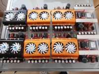
I can post a small clip with my SMPS full-bridge hard switching based on a ETD49 core 3C90.
9A at 110Vdc almost 1 kW. Not bad in my opinion.
https://www.youtube.com/watch?v=eMJUEA1k8cg
https://www.youtube.com/watch?v=56iD4KfRcjQ
If you have some tests with your prototype you can post?
Best regards,
Mircea.
Last edited:
Can a 555 timer be used in an isolated flyback topology to make a variable power supply by varying the duty cycle? Or should the mains voltage be stepped down to a lower value like 30-40V and then made variable with a buck converter?
Can a 555 timer be used in an isolated flyback topology to make a variable power supply by varying the duty cycle? Or should the mains voltage be stepped down to a lower value like 30-40V and then made variable with a buck converter?
Yes, but you need 2 control loops to achieve both voltage and current regulation. An uc3843 is much simpler, and not more expensive.
- Status
- Not open for further replies.
- Home
- Amplifiers
- Power Supplies
- Questions about building SMPS