"series cap (for 1st order highpass)---Paralleled resister(to give the cap a kind of stable load to work off)---series resister(to attenuate and drop some high end off)---piezo tweeter(hopefully more tamed piezo) "
You're talking about using Andy's method, but remember this is going to change the output relative to frequency. You will have a little attenuation at mids and a lot of attenuation on the high end.
My method has a fixed level of attenuation across the frequency spectrum.
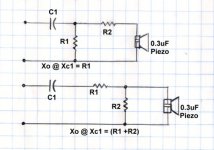
Refer to the attached diagram.
Andy's method is valid, if that is what you are trying to accomplish. Also note that relative to the crossover frequency, the second resistor R2 doesn't come into play. The crossover is calculated using only R1.
If you use Andy's method, there is going to have to be a degree of experimentation to get the right R2 value. In my previous example I used 50 ohms for R2, I think that is too big, you are losing 65% of the signal at 20khz. 20 to 30 ohms would be better; R1 roughly 20 ohms and R2 roughly 30 ohms. This should cause less loss of highs, but still soften the sound a little.
In Andy's example, the crossover is calculated strictly based on R1, which in our current example is 20 ohms.
In my fixed attenuation example (as shown in the diagram) the attenuation is constant across the frequency spectrum, and the crossover is determine by considering the values of both R1 and R2. In this example of fixed attenuation, I suggest using the same resistors; R1 = 20 ohms and R2 = 20 to 30 ohms. A 20 ohm R2 will give you a 50% attenuation which is about where I have mine set now. A 30 ohm resistor will give you about a 40% attenuation, leaving 60% of the signal across the Tweeter.
I don't have the same Piezo as you do, but for my speakers, 40% signal to 60% signal across the tweeter is about right.
So, do you want variable attenuation across the frequency spectrum with a little in the midrange and a lot in the high range, or do you want fixed attenuation across the complete frequency spectrum. Both are valid, it is just a matter of what you want.
Based on the woofer you have, Xo=2khz is probably the best compromise. Though I might personally be tempted to squeeze it up to 2.1k or 2.2khz, but that's just me.
Steve/bluewizard
You're talking about using Andy's method, but remember this is going to change the output relative to frequency. You will have a little attenuation at mids and a lot of attenuation on the high end.
My method has a fixed level of attenuation across the frequency spectrum.
Refer to the attached diagram.
Andy's method is valid, if that is what you are trying to accomplish. Also note that relative to the crossover frequency, the second resistor R2 doesn't come into play. The crossover is calculated using only R1.
If you use Andy's method, there is going to have to be a degree of experimentation to get the right R2 value. In my previous example I used 50 ohms for R2, I think that is too big, you are losing 65% of the signal at 20khz. 20 to 30 ohms would be better; R1 roughly 20 ohms and R2 roughly 30 ohms. This should cause less loss of highs, but still soften the sound a little.
In Andy's example, the crossover is calculated strictly based on R1, which in our current example is 20 ohms.
In my fixed attenuation example (as shown in the diagram) the attenuation is constant across the frequency spectrum, and the crossover is determine by considering the values of both R1 and R2. In this example of fixed attenuation, I suggest using the same resistors; R1 = 20 ohms and R2 = 20 to 30 ohms. A 20 ohm R2 will give you a 50% attenuation which is about where I have mine set now. A 30 ohm resistor will give you about a 40% attenuation, leaving 60% of the signal across the Tweeter.
I don't have the same Piezo as you do, but for my speakers, 40% signal to 60% signal across the tweeter is about right.
So, do you want variable attenuation across the frequency spectrum with a little in the midrange and a lot in the high range, or do you want fixed attenuation across the complete frequency spectrum. Both are valid, it is just a matter of what you want.
Based on the woofer you have, Xo=2khz is probably the best compromise. Though I might personally be tempted to squeeze it up to 2.1k or 2.2khz, but that's just me.
Steve/bluewizard
Attachments
Upon giving it some second thought, even if you use my fix attenuation method, it still might be wise to put a small 5 ohm to 10 ohm resistor in series with the Piezo. Not only would this soften the highs and smooth out the frequency response, it would protect the circuit at very high harmonic frequencies.
Using your Piezo as an example, at 200khz the relative impedance is down to 2.65 ohms, that's pretty low.
At 20khz, a 5ohms resistor is going to produce 16% attenuation, a 10 ohm resistor is going to produce a 27% attenuation in addition to the fixed attenuation created by R1 and R2 in my circuit.
At 2khz, 5 ohm = 1.9%, 10 ohm = 3.6%
At 200khz, 5 ohm = 67%, 10 ohm = 79%
So, one could combine the circuits so you had a fixed level of attenuation to match or balance the outputs of the tweeter to the woofer, and series resistor to soften the highs and protect against ultra-high frequency short circuit.
Sounds more appealing all the time.
Steve/bluewizard
so if I choose a fixed network I shall try
by amps view
series Cap---series res---parallel res---series res---tweeter
cap and first 2 res, provide crossover and some attenuation across full spectrum, and last resister smooths softens and add a bit of protection for the circuit
I will use this circuit 🙂 I play with the r2 value a bit when I get the parts thanks for your help
With that in mind do I calc the cap value from crossover frequency impedance by the total of R1 + R2 ( for ex 20 and 20, so put in 40 in a calc program)
Very much appreciated
Thanks Cya
I suppose I could actually open up the Little Coffins (Eminence Gamm 12 + Ksn1141 with squarish horn). They have done a couple of hundred gigs without issue, always sound good. They are a bit hard to get inside though, so maybe not !!
I think the final resistor was about 30 ohms, but can't be sure.
I think you may find that first resistor a bit much. although I think you did mention your woof was only 91dB ?
I think the final resistor was about 30 ohms, but can't be sure.
I think you may find that first resistor a bit much. although I think you did mention your woof was only 91dB ?
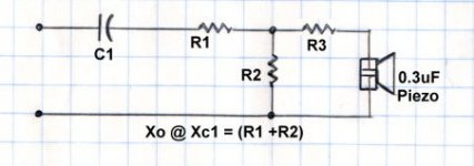
I've attached a new drawing for a circuit that is a combination of my idea and Andy's idea. I've added R3 for the resistor in series with the Piezo.
The values of R1 and R2 can be just about anything, all you are really doing is making a voltage divider. Though realistically, we want to stay in single digit to low double digit numbers.
So, for this voltage divider it is the ratio of one resistor to the other, and not the actual values. With R1=20 and R2 =30, we have 40% dropped across R1 leaving 60% of the signal available to R2 and equally for (R3+piezo). But the same thing could be accomplished with 10/15 or 40/60. Though 40/60 might be getting a little high.
I think likely you are going to want 50% to 70% of the signal to get through to the Peizo+R3 combination. So the formula is simple -
Rs = R2/(R1+R2)
As an example-
Rs = 30/(20+30) = 30/50 = .60 = 60% signal to the tweeter
Rs = 20/(20+20) = 20/40 = .50 = 50% signal
Rs = 50/(20+50) = 50/70 = .71 = 71% signal
The point is, it's not the actual values, it is the ratio of the resistors. Though I think rather than use 20+50, I might be more inclined to use 10+25 to give the same ratio for R1+R2, but a lower general impedance.
The value of R3 only works for this particular Piezo tweeter. For other piezo tweeters, we either need the capacitive equivalent or and impedance response chart for the tweeter.
From that we can determine the proper value of R3 by calculating the relative impedance of R3 at different frequencies and figuring out how much signal will be dropped across the piezo.
Note, there is a phase shift between the pure resistive voltage and the piezo-capacitive voltage. We are ignoring this, but in this case, I don't think the phase is critical. For R3 all we need is an estimate of the attenuation at any given frequency.
I know some Piezos have very high impedance; I've been generally lead to believe in the range of few hundred to a few thousand ohms.
In my previous post, I gave estimated attenuation for various resistors (5 ohm and 10 ohm) for THIS piezo. Other piezos would likely need different values. That's why it is nice to have the data sheet on the specific piezo you are working with.
To calculate the Capacitor you need for this new circuit, see the formula below -
Where -
fo = the crossover frequency
(pi) = 3.14159
C = the required capacitance
C = 1/ [2 (pi) fo (R1+R2) ]
C = 1/ [6.283 x 2000 x (20+30)]
C = 1.59 x 10^6 or 1.59 micro-Farads
Adjusting the resistor values but keeping the same ratio of resistors could bring the capacitor into a more ideal value.
Andy, you mentioned using your speaker set at 'gigs', are you DJing or is this for a band. If it is for a band, I want to point out the Producing music is a very different animal than RE-producing music. I can see why you would want to emphasize mid and tone down highs if this is the case.
For music reproduction, I think you are going to want a flatter response. But as this discussion has gone on and I looked at the frequency response chart of this Piezo, I think the addtion of R3 is a good idea in any case.
Personally, I would prefer to replace R1 and R2 with an L-Pad, but if you can hit the right R1+R2 combination, that's good too. To each his own.
steve/bluewizard
Attachments
- Status
- Not open for further replies.