Hello,
I want to make a 1st order low pass and high pass for a 2 way system, Im going to make it for some simple learning and fun
It involves a 10" mid bass and a high power horn tweeter
I know all the crossover involves is a single capacitor and single inductor of a certain value for a 1st order (unless you series some smaller values to get your target value)
When I find some or read inductor specs they have the reading of resistance of like between 0.1 - 2 ohms, to me that is a lot, which will make my final load over 8 ohms to my amp giving me less power
My questions: How do I, you or manufacturers keep the total load to your specific level of 8 or 4 or whatever you use, because when I measure my current speakers they have a load of 8.0 ohms and they are 2.5 way
When making a passive crossover accurately do you break in the woofer first then measure what the impedance is at the frequency you want to cross then put that impedance value in a crossover calculator?
Im only just starting to learn about frequency impedance
Thanks Cya
DCR is not impedance, though it is a contributor. Impedance varies with frequency.
Manufacturers do not typically adjust impedance in the manner you suggest; it is what it is, and the nominal 8 Ohms spec is often, but not always, the minimum impedance across the frequency spectrum. In lowpass filters, it's usually desirable to minimize the inductor DCR.
Yes, in designing filters, use the actual impedances of the drivers at the target frequency, but ultimately, it's the acoustic crossover performance that counts, i.e. the electrical as combined with the driver(s) frequency response through the crossover region in the final alignment.
Thanks you 🙂 you clarified what I read, This stuff is interesting
Ive just searched the forums and there have been plenty of people doing what I want to do, and thats use a 10 - 12" driver with a piezo tweeter for a simple 2 way system, but the one thing they all have in common is they didn't want to use crossovers even 1st order, which requires no real extra work and will do wonders in making the project better,
But like them I need a little help,
Im using a 10" woofer and piezo tweeter of sorts, I live in Australia and I am limiting myself to Aussie shops for ease of use,
from what I read if going passive you use parallel crossovers, both units have a nominal impedance of 8 ohms and I'm using 1 of each and want to keep it roughly 8 ohms to the amp,
This brings another question: If I use a parallel type, will that make the nominal load be 4 ohms in practice or does it somehow stay 8 ohms
Or am I expected to use 2 of each in each speaker and then series the 2 tweeters and 2 woofers together to make a 16 ohm then paralell cross them to make a nominal 8 again?
Sorry If im being confusing, its just all this series and parallel stuff with crossovers is new to me
Thanks Cya
Just out of curiosity, why don't you just buy a ready made crossover? Here in the USA, they are about US$20 each, or a simple high-pass filter for less than US$10 each.
Yes, that does add to the cost of the speaker, but it produces a better speaker.
Piezo tweeters typically have an impedance of about 3k ohms (to the best of my memory).
You need a capacitor in series with the piezo to filter out lows, and you need a resistor combination (one series, one parallel) to balance the volume between the woofer and the tweeter. Personally I just use a L-Pad so it is easily adjustable.
Some people, myself included add a parallel resistor across the Piezo terminals to stabilize the impedance. I think I have 10 ohms across mine, but I have mine connected to a 3-way crossover and the crossover assumes that it is working with a roughly 8 ohm speakers.
Which brings up the final point, speaker impedances are all over the place. An 8 ohm speaker is 'nominally' 8 ohms, which means 'sort of' 8 ohms. The impedance across the operating frequency range will drop slightly below 8 ohms and go substantially above. However, I have seen consumer Hi-Fi speakers that drop as low as 3.5 ohms but are still rated as 8 ohm nominal.
If you search the Internet, you will find instructions on how to properly create a crossover, impedance stabilizer, and level control for a piezo tweeter.
steve/bluewizard
Yes, parallel. Another case wherein all is not what it may seem.Toast_Master said:This brings another question: If I use a parallel type, will that make the nominal load be 4 ohms in practice or does it somehow stay 8 ohms
The lowpass filter is high impedance at high frequencies, and the highpass filter is high impedance at low frequencies, so it's only in the crossover region that the actual impedances of both drivers are in parallel, and the system impedance there is the combined impedances of the drivers, which may not be the nominal, and the filters.
Build it and measure the network impedance with the drivers in their final alignment as load.
My message: No textbook or off-the-shelf network is going to perform according to "design" but with ideal drivers. You either have to input all of the variables into crossover modeling software, or empirically optimize a theoretical design using system performance measurements....
Thanks but I wont Buy a pre-built crossover, I'm doing this to learn and have fun building it and Im keeping it simple for a 1st project of this nature,
what I have learned is piezo tweeters are very high impedance across there working range and after a certain level, 30 - 100khz they drop as low as 1 ohm and present problems to amps that run them
What I have read is to parallel an 8 ohm resister to stabilize the impedance, then before this paralleled 8 ohm resister is an 8 ohm L-pad,
Is this L-pad an attenuator of some sorts? to lower the piezo's efficiency, what is this L-pad what component is this
To make it easier for you to help me, Im going to use the
KSN1141A Piezo Tweeter and I'm going to 1st order highpass it at approx 2khz
So to make this usable and not so bad, im going to need some help from you guys I will try and understand to the best I can
So can someone help me with The L-pad and the circuit as a whole
I have a slight Idea of circuit order, the 1st order high pass, then the 8 ohm L-pad then the paralleled 8 ohm resister, is there more I need to add
Thanks Cya
An L-Pad is a constant impedance volume control for your tweeter.
In my case I have a 12" woofer, 3x9 mid-horn, and a 3x3 Piezo tweeter. The Tweeter is noticeably louder than the mid-horn, so I turn down the L-Pad until the relative volumes match.
An L-Pad always presents a constant load to the amp or to the crossover network regardless of where it is set. At full volume, you have a 600 ohm resistance in parallel with the amp and the tweeter. 600 ohms is substantially large enough to be effectively out of the circuit.
When the L-Pad is turned all the way down, the amp sees an 8 ohm load, and the tweeter is effectively out of the circuit. Thus maintaining a constant 8 ohm load to the amp/crossover across the full range of adjustment.
Because you will calculate your crossover frequency based on a known speaker load, you have to know what that load is.
You can put any resistor in parallel with the Piezo and use that resistor load to calculate your crossover components. Though, certainly some equivalent loads will produce ridiculous numbers for capacitors and coils.
I would say a capacitor connected to the L-Pad would insure stable cross over frequencies and limit the signal level to the piezo. I think the Piezo you picked has some built-in protection circuit to keep dangerous signal levels off of it, but it doesn't hurt to be cautions.
If you read the article linked to above by Peter, the Piezo page indicates that it is not necessary to terminate the piezo with an 8 ohm resistor. To some extent that is a waste of power. You could terminate the piezo with a 15 to 25 ohm power resistor and use a 16 ohm L-Pad, I think that would work fine.
16 ohm L-Pad
http://www.partsexpress.com/pe/showdetl.cfm?&Partnumber=260-254
I think even with the 10" woofer, the piezo is still going to be too loud and will definitely need an L-Pad to bring it down.
One other reason to put a resistor in parallel with the Piezo it that to the amp, unless I am mistaken, the Pieze looks like a capacitor which complicates matters.
Probably not much help, but there it is.
Here is a link to a Parts Express 3-way project that uses a 3x7 Piezo horn, and an attached link to the crossover network.
Golden Boy Speaker Project -
http://www.partsexpress.com/projectshowcase/goldenboys/driver.cfm
Golden Boy Crossover-
http://www.partsexpress.com/projectshowcase/goldenboys/crossover.jpg
You are only concerned with the upper section. The 20 ohm and 33 ohm resistor present a stable 53 ohm resistive load to the .22 uF capacitor/crossover. The 20 ohm and 33 ohm also lower the signal to the piezo tweeter by about 38% (leaving 62% to the tweeter).
A combination like this allows for all the necessary considerations, but I still personally prefer an L-Pad so I have a full range of setting for Tweeter volume.
Steve/bluewizard
I have read your helpful posts and Im going to consider them very much, It seems not complicated at all to improve a piezo tweeter with little effort, ok, can I generalize this info and use it as is because I have no way of measuring impedance at frequency's in piezo,
another question:
should or can I use a High pass on the woofer in the passive crossover?
A simple 1st order one is all I want to use so I get more power handling from it, and so I can tune it higher so I get more spl without the risk of increasing excursion at lower frequencies if there present in the music,
I ask that because I never see them in speaker designs of passive crossovers on this site or in pre made ones, Are they not required because of what?
Thanks so far for all your input,
Thanks Cya
KEF are famous for adding a high pass to their speaker crossovers to improve their sound.
There will be others adopting this for at least some of their models.
There will be others adopting this for at least some of their models.
With a 6db slope I don't see much point to a high pass on the woofer. Although, I might not understand what you are really saying or intending.
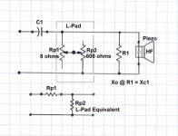
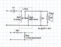
Attached is a drawing showing what your circuit should look like -
The Crossover occurs when the reactance (resistance equivalent) of the Capacitor equals the resistance of R1 (resistor across the piezo).
Your Piezo, unless my specs are wrong, has a natural crossover at abut 1.4khz which makes me wonder if your suggested 2k crossover is enough. If your woofer has sufficient frequency responce maybe 2.5k hz or 3k hz would be better. You need to remember that 6 db slope is very shallow and significant sound will occur far below and above the crossover points.
Because the crossover is so shallow, you could try tweeking the crossover points a bit. For example, the woofer could crossover at 2.2k hz and the tweeter could crossover at 2.0k hz. Though without a lot of components to play with or a computer modeling program, that might be too complicated.
The diagram I have enclosed is for a Parallel 1st Order Crossover, meaning, a capacitor in series with the Tweeter and a coil in series with the woofer. I think this is the most common type.
Also, as I already pointed out, you could use either an 8 ohm R1 and 8 ohm L-Pad, or a 16 ohm R1 and 16 ohm L-Pad.
Amended: Sorry, I just noticed an error in my diagram. It is the 'wiper' of the L-Pad that should go to the Tweeter.
Rp1 is connected to the capacitor and amp,
Rp2 is connected to ground,
the Wiper is connected to R1 and the Piezo.
steve/bluewizard
Attachments
Toast_Master said:Thanks but I wont Buy a pre-built crossover, I'm doing this to learn and have fun building it and Im keeping it simple for a 1st project of this nature,
what I have learned is piezo tweeters are very high impedance across there working range and after a certain level, 30 - 100khz they drop as low as 1 ohm and present problems to amps that run them
What I have read is to parallel an 8 ohm resister to stabilize the impedance, then before this paralleled 8 ohm resister is an 8 ohm L-pad,
Is this L-pad an attenuator of some sorts? to lower the piezo's efficiency, what is this L-pad what component is this
To make it easier for you to help me, Im going to use the
KSN1141A Piezo Tweeter and I'm going to 1st order highpass it at approx 2khz
So to make this usable and not so bad, im going to need some help from you guys I will try and understand to the best I can
So can someone help me with The L-pad and the circuit as a whole
I have a slight Idea of circuit order, the 1st order high pass, then the 8 ohm L-pad then the paralleled 8 ohm resister, is there more I need to add
Thanks Cya
I have used the KSN1141 quite a bit. Usually I have used Eminence 12" Gammas with them.
The x-o is fairly simple.
Just put a .56mH coil in line with the bass to roll off the top end.
Then use the circuit below with R1=22 ohms C1=3.9uF
R2 is then going to be used to balance the bass and tweeter, and will probably be around 30-50 ohms. It depends on the efficiency of the bass driver.
ps: do not use an 8ohm parallel to the piezo, you will drop its level too much.
Attachments

What do you mean do not use an 8 ohm resister, "It will drop its level too much?" the ohm level or its spl? cause I thought having more ohms will drop it too much? can you explain?
Thanks Cya
Thanks Cya
I'll let Andy speak for himself, but think he is generalizing. By that I mean, he is not being really specific in his choice of words.
Putting an 8 ohm resistor in parallel with the Piezo will not reduce the signal level. Since they are in parallel both components get the exact same signal (or voltage). But since the Peizo is several hundred to a few thousand ohms, if is not drawing much current. The 8 ohm resistor, however, would be wasting some current unnecessarily. But keep in mind that it won't waste any more current than an 8 ohm speaker would have.
Since we have a nice high impedance tweeter, we might as well take advantage of it.
Notice the link I gave to a sample crossover that used a Piezo tweeter. They used a 20 and a 30 resistor (roughly) to drop the signal to about 60% of the original. Again, this is just another way of accomplishing what an L-Pad accomplishes. The problem is, a resistive network like this is fixed, so you better plan to have several resistors on hand to get the levels balanced between the woofer and tweeter. Again, for $10, it's much easier and more versatile to use an L-Pad.
So, in the example I linked to, the total load seen by the capacitor is 50 ohms (roughly), to find the crossover frequency, simply find out at what frequency the Capacitor is equal to the resistor. Notice that Andy also suggest using a 30 to 50 ohm resistor. Though to some extent I question whether his circuit is working the way he thinks it is.
Now my personal opinion, is that you use the configuration in my diagram, and to reduce wasted current, use a 16 ohm L-Pad and a roughly 16 ohm resistor.
Just a few thoughts.
Steve/bluewizard
Toast_Master said:What do you mean do not use an 8 ohm resister, "It will drop its level too much?" the ohm level or its spl? cause I thought having more ohms will drop it too much? can you explain?
Thanks Cya
Think.. if you put a near zero resist0r ACROSS the piezo, how much output do you think there would be??
If you put infinite resistance across, you get full output.
I have tried using an 8ohm resistor across the KSN1141, and it did not produce enough upper mids and top end to keep up with a pro woofer. Using 22ohms, it does. The R2 resistor in the circuit I posted is sort of a trimming resistor.
Remember that there is also a capacitor involved, which can be a lower value (less cost) if a 22ohm resistor is used across the piezo. You can calculate the value of the capacitor by assuming that the capacitor sees a resistance at x-o of a bit less than 22ohms.
you both have different way and they both seem simple and effective, slightly different, kinda understand both, But I dont think L-pads are available here or they have another name, if there not available will follow the fixed network way because the parts are available right away,
Thank you both 🙂
I think I should give you the woofer specs so you can speculate on how much I should trim because the woofer I'm using is'nt that sensitive but it does play low enough for me and in a pretty small enclsore
The specs: only ones I can find
- Nom impedance: 8ohms
- Power handling: 160watts RMS
- Frequency range: 29Hz - 2500Hz
- Sensitivity: 91dB 1watt 1metre
- Voice Coil Resistance (Re): 6.9ohms
- Resonant frequency (fs): 29Hz
- Mechanical Q factor (Qms): 7.632
- Electrical Q factor (Qes): 0.364
- Total Q factor (Qts): 0.347
- Equivalent Volume (Vas): 98Lt
- Cone Area (sq m): 0.0346
I assume its x-max is 5 mm or less so I have been using that as my base line
I have probably gone the wrong way about this but I was using winisd for the low end sim so see what size box and tuning would give me low enough FR and be able to play loud enough for my taste for the low cost of it to be diy
If you know of a much better woofer any size 10 - 12" that will play just as low (45hz - 3db) that is more sensitive and has a high power handling that Is available to me in Australia and is no more than $100 AU
Also another question lol
How do you usually calculate a cap, resister or coil to have enough power handling for a certain wattage, my amp can put out 120 watts rms, of course I wont be using this max all the time or at all, but yeah you get me? I want values that can withstand that and know how to in future so if I power this by a much more powerful amp I can know the levels,
Also with that question, does the power handling ability of the components affect the signal in anyway, like say it required a 100 volt cap to withstand 100 watts, would a 300 volt plus cap of the same brand and cap affect it differently?
Thanks Cya
Here is a link to the manufacturer's spec sheet on this Peizo tweeter -
http://piezosource.com/general/datasheets/Piezo_1141_datasheet.pdf
This didn't work well when I tried to load it in my browser, but was OK when I downloaded it to my computer and opened it with Adobe Reader.
Notice the frequency response curve. It starts to drop pretty sharply at about 2k hz. I still think a 3khz crossover would be better if your woofer goes above that.
This Piezo appears roughly as a 0.3uF (0.3 micro-farad) capacitor. Based on calculations, that means 265 ohms at 2khz, 26.5 ohms at 20Khz, and 2.65 ohms at 200khz. The impedance curve at the bottom of the data sheet roughly bears out those calculations.
Using my circuit with a 16 ohm Resistor in parallel to the Tweeter, the combined impedance of the resistor and the tweeter is roughly -
@ 2khz = (16 X 265)/(16 +265) = 4240/281 = 15.1 ohms
@ 20khz = (16 x 26.5)/(16 + 26.5) = 424/42.5 = 9.98 ohms
This doesn't allow for a slight phase shift between the resistive and the capacitive, but it's close enough for an estimate.
Calculation for Capacitive Reactance -
Xc = 1 / (2 (pi) f C)
Calculation for Inductive Reactance -
Xc = 2 (pi) f L
So, in Alan's circuit, an R2 value of 50 ohms is going to consume about 16% of the signal applied to R1 at 2khz (50/(265+50)=0.16). At 20khz, R2 is going to drop about 65% of the available signal (50/(26.5+50)=0.65).
So, Alan's circuit isn't really boosting Mids so much as it is cutting Highs.
Though, notice from the frequency response curve that some attenuation between 5khz and 20khz is not a bad thing. I does level the frequency response curve.
Here are some links to general Piezo Crossover discussions-
General First Order Crossover Networks-
http://www.colomar.com/Shavano/crossover6db.html
Piezo Tweeter Application Notes-
http://www.pulsardevelopments.com/products/detail/piezoan.html
AudioKarma Forum: Using piezo tweeters wisely: a "how to" -
http://www.audiokarma.org/forums/showthread.php?t=79659
Google Books: Great Sound Stereo Speaker Manual-
http://books.google.com/books?id=rv...ts=EoX4oFPMI7&sig=3TlNwv51CzEAbf9wvGtc4ZXdiuE
Between these links and the data sheet for your Piezo, you should have every thing you need.
Steve/Bluewizard
Thanking you Bluewizard,
I have read about 2 of those before you posted them, still the reason I'm so unsure is that some say don't use a series resister and some say do it....lol
also all have a cap first, then either a series resister or a parallel resister then another resister the opposite way from the first resister, other and thats with L-pads as well, what am I supposed to take as the right way...maybe all of them and maybe I just pick one or experiment but I shouldn't have to if one of you has used a piezo already and has experience, next time i'm at work Ill check if I can order in L-pads and If I cant can some one help me, If not Ill just follow one of the explained methods as close as I can and hope it works as well for me 🙂 lol
So far, without an L-pad to work with I have to assume im not using one for now,
so for now correct if im wrong or speculate
saying it this way cause I dont have a crossover drawing program
from the amps view on positive line,
series cap (for 1st order highpass)---Paralleled resister(to give the cap a kind of stable load to work off)---series resister(to attenuate and drop some high end off)---piezo tweeter(hopefully more tamed piezo)
my explanation: the cap value is calculated at the frequency and impedance at slightly lower than the next paralleled resister, then the next series resister is calculated on hom much you want to drop the spl by?
Omg this must be annoying for yous, but there are so many source saying different info, I enjoy the reading though 🙂
Thanks cya
- Status
- Not open for further replies.
- Home
- Loudspeakers
- Multi-Way
- Question/s about passive crossover and components?