I'd like to build Pete Millett's 6B4G PP amp where he uses 1.5k wirewounds tied to ground per each 6B4G filament connection without bypass capacitors.
It seems to me that for the cathode bias of 6B4G without bypass capacitors, the internal resistance will be increasing to more than 2Kohm. Is there any benefit in doing so, especially in an ouput stage? I know that for the preceeding stage(s) we can use that technique to lower distortion (gain also). I see in other amps that in most of them with cathode bias, they'd use bypass capacitors.
Thanks for your help!
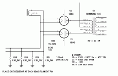
Actually, if you look close, and consider that the 6B4 filaments are effectively a dead short, the cathode bias is made with four paralleled 1K5 resistors. For push-pull class A triode stages only tiny (hopefully! because it means that the stage is well balanced) signal voltage appears across the cathode resistor. This is very similar to the way that only small signal voltage appears across the B+ supply.
All good fortune,
Chris
All good fortune,
Chris

I think the OP's concern must be about increased source impedance at the anodes, but this is class A push pull, so it doesn't happen.
All good fortune,
Chris
All good fortune,
Chris
> the internal resistance will be increasing to more than 2Kohm
I see 375 Ohms?
I think the OP's concern must be about increased source impedance at the anodes, but this is class A push pull, so it doesn't happen.
All good fortune,
Chris
Thanks PRR, Chris!
It dawn on me that I was worried about increase source impedance at the anodes not the internal impedance of the tube (my tube knowledge is somewhat limited). Now that I know due to you clear explanation above.
Thanks again!
If you want it to always be Class A push pull, then remove those resistors.
Instead, use a current sink from the two 300B filaments end to ground.
No matter how hard you drive the grids, the On tube will never have more current than two times the quiescent current of one tube.
That is because one tube is cut off, and the other has all the current that is dictated by the current source.
You will have soft clipping as the hard driven grids try to enter the B portion of Class AB.
Any drive level lower than that point is Class A.
All this does require that you do Not use a bypass cap.
But if you use resistance from the two 300B filament end to ground, as in the schematic,
When the driver tubes outputs enough voltage, one tube will cut off; but then with more drive voltage, the other tube will have more than 2X its quiescent current (real Class AB).
To keep a push pull amplifier in class A, does require special design to prevent one tube from cutting off.
Last edited:
- Home
- Amplifiers
- Tubes / Valves
- Question regarding power tube unbypass cathode resistor