I've been told many times and have read many places that the Williamson push-pull amplifier topology is inherently unstable. But... I'm not sure if that's a valid blanket statement.
It isn't
1. Of course it's true that the Williamson design has a lot of RC-coupled stages, with multiple poles. Also, the OPT adds another pole. If two poles are close in frequency but out of phase, and the usual 20dB of global negative feedback is applied, oscillation will surely result. But...
- What if the poles are staggered so that no two poles are too close to each other in frequency?
SoP for any competent design. Staggering the time constants of C-R couplings definitely keeps phase shifting from piling up.
- What if MOSFET source followers are added after the differential driver stage, so that the F3 of the RC network between the diff driver and output stage can be chosen so as to be far away from other F3 points in the circuit?
I like final grid drivers, but not for that reason. C-R coupling to the finals can lead to distortion on clipping. Once the CGK parasitic diode is turned on, negative grid voltage increases (in a negative way) that puts the finals into a less linear region of the plate characteristics until that extra voltage bleeds off. This is how RF amps derive some -- or all -- their working grid bias.
- What if there is much less NFB wrapped around the circuit? Let's say only 6dB of global NFB applied?
Then it's not a Williamson. That was the whole point behind the design: more gNFB than anyone had used before. The main problem with replicating this design isn't low frequency stability, as that's easy to deal with. The high frequency stability? Not so much. The Partridge OPT used in the original Williamson had a much wider BW, well above 100KHz, and that was necessary considering all the gNFB. You'll probably be needing more than 6dbv of gNFB to make a noticeable difference.
The other possibility would be to remove one set of RC time constants, by DC coupling the differential driver stage plates to the output stage grids. This would require a center-tapped choke be used as the plate load for the diff/driver pair, and for the cathodes of the output tubes to be raised at least a couple dozen volts higher than the diff/driver plates. I have done that by 'stacking' the driver stages' plate DC supply on top of the output tubes plate DC supply, but with output tubes with 400V plate-to-cathode, the total supply voltage would get up there at about 800V DC. That's getting dangerous.
I considered it: "sinking" the last voltage amp below 0V so that the plate voltage was at the bias for the finals. It's NBD these days with SS diodes to make a negative auxiliary supply. All that's required is to preserve the VPK. It becomes a real PITA to keep VHK in spec, and may require the heaters of the drivers to have a dedicated heater PTX to allow for enough DC to be applied to keep VHK in spec.
For eliminating one coupling cap,
one could use an N channel and a P channel Mosfet Concertina pair, and take the out of phase outputs from the ground referenced side of each.
Some Zener biasing still needed in the previous load R to give the Concertinas operating range though.
One could also optionally cross couple some caps between the equivalent phases of each splitter to make sure they are doing exactly the same thing. Some gate protection diodes may be a good idea.
Last edited:
I remember hearing a pair of Heathkit W5M amps, which were Williamson style PP UL 6L6 with 12AU7 driver tubes, Acrosound TO series OPTs. Probably of a similar design. Those Williamson amps sounded 'vintage' too. Kind of mellow, romantic, maybe 'slow'. Pleasant, though.
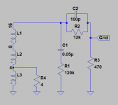
Looking at the schematic, those have the standard high frequency step filters on the plate of the input stage and the bypass cap around the negative feedback resistor.
Heathkit W-5M
So, being that this is a derivative of the Williamson design, but not exactly the same thing as the original Williamson design, is this a "Williamson" amp?
- What if there is much less NFB wrapped around the circuit? Let's say only 6dB of global NFB applied?
Then it's not a Williamson. That was the whole point behind the design: more gNFB than anyone had used before.
Well then, that's the answer!
So now my question morphs into, what do we call the general driver stage topology? The cathodyne into diff driver... Is that a "Williamson driver" circuit?
The original OPT's used by Williamson were custom made circa 1944-5, and likely built with the assistance of Vortexion as they were the closest manufacturer to where Williamson worked at Marconi-Osram in London. Partridge had an OPT commercially available about 4 months after the original 1947 WW article (which included base OPT design details). The Partridge WWFB was commercially available from the Aug 1949 WW publication of Williamson's update (or 'new') series of articles, so over 2 years after the original WW articles. Very few Partridge OPT's that were made to Williamson's original design appear to have survived, and it was the latter WWFB OPT that seems to have cemented Partridges reputation.The Partridge OPT used in the original Williamson had a much wider BW, well above 100KHz, and that was necessary considering all the gNFB.
I remember hearing a pair of Heathkit W5M amps, which were Williamson style PP UL 6L6 with 12AU7 driver tubes, Acrosound TO series OPTs. .... So, being that this is a derivative of the Williamson design, but not exactly the same thing as the original Williamson design, is this a "Williamson" amp?
Perhaps it is simpler to refer to any derivative amp as just that, a derivative. It is certainly worthwhile to propose and/or make and measure derivatives and detail the changes both from a design perspective and a measured perspective. One observation is that few if any derivatives have had their technical details and performance fully described (to the nitty gritty level where a detailed comparison with the original concisely describes all the changes along with technical details).
Last edited:
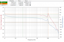
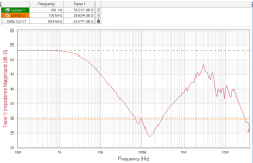
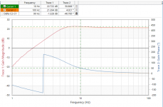
This appears to have been a Heath wired amplifier -- has a somewhat different compensation/feedback scheme than in the schematics I've seen. I injected a test signal into the 16 ohm traf output and plotted the impedance (with a 4 ohm dummy load).
Attachments
An interesting discussion!
As one who originally built Mullard 5-20's back in 1965 and visited some hifi enthusiasts who had built Williansons (KT66's) with Red Line output transformers designed to DTN's specifications, the difference in sound was considerable. The class A triode amps were musical whereas the Mullards were upper middly. With preamps the Baxandall and Leak tone control ccts were far better than the Mullard.
Please excuse the musings from a fairly ancient hifi fan who is an avid DIYer.
Jackinnj, that frequency response indicates unstable HF operation due to zero phase margin and no gain margin, and that resonance is not insignificant. The VNA needs to go down to at least 1Hz to get an indication of LF stability.
Jackinnj, that frequency response indicates unstable HF operation due to zero phase margin and no gain margin, and that resonance is not insignificant. The VNA needs to go down to at least 1Hz to get an indication of LF stability.
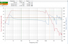
Will do that tomorrow morning. VNA goes 1Hz to 50MHz. Will show gain and phase.
Ta muchly jackinnj. Nice bit of kit to be able to do those wide-bandwidth plots !
The previous plot of phase made it difficult to discern the 180 deg HF crossing, but this recent plot sort of makes that frequency easy to discern now at about 220kHz, where gain is still about +6dB (!). Going out beyond 1MHz sort of shines a light on whether your resistive load is still pretty much resistive - I typically use PRO2 range of resistors with the comfort that the datasheet shows negligible reactance out to 10MHz.
The LF end shows only a slight peak at around 8Hz, with 180 deg at 3Hz but still with about +7dB gain margin. It suggests the CR networks are dominating the LF response and the OPT LF corner is a lot lower and below 1Hz.
Peteki, it's interesting that you bring up the Red Line OPT range for the Williamson amp. I did a batch of tests on them earlier this year - https://www.dalmura.com.au/static/Williamson%20output%20transformer%20measurements.pdf - and an AF8/2 example only showed fair performance with parameter measurements not meeting Williamson's benchmark levels or the claimed levels in their adverts of the time.
- Home
- Amplifiers
- Tubes / Valves
- Question re: Williamson amplifier and stability