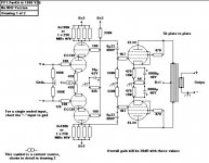
I have a donor amp that can easilly become the PP-1.
However I'm a little confused by the B+ indicators
On the schematic there are two B+2 at the top and a B+3 on the anode of the lower ECC88.
Shouldn't the lower one be B+2 and the right B+2 at the top be B+3?
Cheers
However I'm a little confused by the B+ indicators
An externally hosted image should be here but it was not working when we last tested it.
An externally hosted image should be here but it was not working when we last tested it.
On the schematic there are two B+2 at the top and a B+3 on the anode of the lower ECC88.
Shouldn't the lower one be B+2 and the right B+2 at the top be B+3?
Cheers
Thanks
Sorry if I am being dense here.
So will both B+2 points in the PSU schematic connect to all three B+2 points in the amp?
Sorry if I am being dense here.
So will both B+2 points in the PSU schematic connect to all three B+2 points in the amp?
Does someone actually know what the voltages at points B+1 and B+2 are?
Especially B+2 as a feed for the Hedge would be interesting: The constant current sink evaluates to about 8mA, thus the voltage drop across the 4k7 resistor between points B+1 and B+2 would be about 40 volts. It would be reasonable to assume about 400V at point B+1, thus B+2 would be at about 360V.
But that would exceed the ECC88 ratings in that Hedge circuit:
8 mA across the 25k plate resistor gives a drop of 100V, thus 360V - 100V = 260V at upper tube plates. Assuming the least worst case scenario each tube section has to deal with 1/2 * 260V = 130V plate voltage which exceeds ECC88 specs a bit...
So, again, does someone actually really know what the voltages at points B+1 and B+2 are?
Tom
Re: Thanks
Yes. If you look, you'll see that the B+2 adjacent to B+1 is the supply; the other B+2 connection is a circuit that needs B+2.
lilolee said:So will both B+2 points in the PSU schematic connect to all three B+2 points in the amp?
Yes. If you look, you'll see that the B+2 adjacent to B+1 is the supply; the other B+2 connection is a circuit that needs B+2.
RE: voltage versus max Va for ECC88, is this a stereo amp? If so, double the drop across the 4k7. Also, I'd expect the B+ to be under 400V given the DCR one might expect from a 10H inductor.
130V is within the max Va spec, but it is admittedly pushing things.
edit: Using a PSUD sim, I get about 390V B+1 for a monoblock, 375V for a stereo pair running off a single supply
130V is within the max Va spec, but it is admittedly pushing things.
edit: Using a PSUD sim, I get about 390V B+1 for a monoblock, 375V for a stereo pair running off a single supply
Re: Thanks
Yes.
The "B+2 point" that is the lower one, coming off the filament supply isn't actually "B+2" at all, it should have an arrow that indicates that it connects TO the "B+2" point. The purpose is to inject 6.3vac antiphase (one would hope) back into the B+ that runs the input stage - thus cancelling the hum component. I am guessing this is the idea.
I'd just switch to DC regulated filaments for these indirectly heated tubes and eliminate the problem at the source. Much better idea.
There are a number of other 'issues' with this circuit.
I don't see any application of fixed bias here. Imho you'll get rather fat and sloppy sound by using self bias and setting the tubes up on top of large electrolytic caps in the cathode. At least bypass them with a largish polypropylene?
Also, the phase inversion balance is likely to be somewhat off if you merely ground the (-) input for single ended input. There are some circuits that provide a solution for this, some are in the Radiotron Designer's Handbook as well as other places. Mostly it is a change to what you do with the (-) input, although there are some things that can be done with the long tail pair's cathode side....
At least I think that's how it might go.
_-_-bear
lilolee said:Sorry if I am being dense here.
So will both B+2 points in the PSU schematic connect to all three B+2 points in the amp?
Yes.
The "B+2 point" that is the lower one, coming off the filament supply isn't actually "B+2" at all, it should have an arrow that indicates that it connects TO the "B+2" point. The purpose is to inject 6.3vac antiphase (one would hope) back into the B+ that runs the input stage - thus cancelling the hum component. I am guessing this is the idea.
I'd just switch to DC regulated filaments for these indirectly heated tubes and eliminate the problem at the source. Much better idea.
There are a number of other 'issues' with this circuit.
I don't see any application of fixed bias here. Imho you'll get rather fat and sloppy sound by using self bias and setting the tubes up on top of large electrolytic caps in the cathode. At least bypass them with a largish polypropylene?
Also, the phase inversion balance is likely to be somewhat off if you merely ground the (-) input for single ended input. There are some circuits that provide a solution for this, some are in the Radiotron Designer's Handbook as well as other places. Mostly it is a change to what you do with the (-) input, although there are some things that can be done with the long tail pair's cathode side....
At least I think that's how it might go.
_-_-bear
Also, the phase inversion balance is likely to be somewhat off if you merely ground the (-) input for single ended input.
Why would that be so if the current source is a good one?
Well,
I am also working on "my" version of the pp1, so the questions discussed here have my full interest...
 )?
)?
And, one final thing, although it is a bit OT for this thread: In solid state design I always used to build fully separate power supplies for both channels, perhaps drawing current from the same transformer, but separate rectification and filtering. How do I handle this in tube circuits? a) one PS for both channels b) one transformer, one rectification, separate filtering c) one transformer winding, separate rectification and filtering or d) two separate PS 😀 ???
Sorry, so many questions... Gladly looking forward to your answers
Greetings
Andreas
I am also working on "my" version of the pp1, so the questions discussed here have my full interest...
If this is really a problem, what possibilities of working around it do i have (no, I do NOT own sources with symmetric outputAlso, the phase inversion balance is likely to be somewhat off if you merely ground the (-) input for single ended input.
)?Am I free to do so? I only build solid state circuits before, where it is usually no problem to bypass a large electrolytic by a foil... If yes, I will do this, should in no way make it worse, i think...I don't see any application of fixed bias here. Imho you'll get rather fat and sloppy sound by using self bias and setting the tubes up on top of large electrolytic caps in the cathode. At least bypass them with a largish polypropylene?
Does anyone have _exact_ values for the current delivered by the ccs. I am going to replace this part of the circuit by a tube based ccs, but I don't have the value of the current needed, it is not given anywhere. Furthermore, as I am not very familiar with tube circuits, what "don't do that!"-statements do I have to care about when building a tube ccs as replacement for the PP1-ccs?The constant current sink evaluates to about 8mA [...]
And, one final thing, although it is a bit OT for this thread: In solid state design I always used to build fully separate power supplies for both channels, perhaps drawing current from the same transformer, but separate rectification and filtering. How do I handle this in tube circuits? a) one PS for both channels b) one transformer, one rectification, separate filtering c) one transformer winding, separate rectification and filtering or d) two separate PS 😀 ???
Sorry, so many questions... Gladly looking forward to your answers
Greetings
Andreas
The "B+2 point" that is the lower one, coming off the filament supply isn't actually "B+2" at all, it should have an arrow that indicates that it connects TO the "B+2" point. The purpose is to inject 6.3vac antiphase (one would hope) back into the B+ that runs the input stage - thus cancelling the hum component. I am guessing this is the idea.
I think the idea is actually to elevate the DC potential of the 6.3v AC heater supply so that it is between the cathode potentials of the two halves of the cascode, as protection against exceeding the heater-cathode voltage limit of the upper triode.
I don't see any application of fixed bias here. Imho you'll get rather fat and sloppy sound by using self bias and setting the tubes up on top of large electrolytic caps in the cathode. At least bypass them with a largish polypropylene?
I believe Allen Wright has brought out a later design, which has a shared CCS in the cathodes of the OP tubes.
Also, the phase inversion balance is likely to be somewhat off if you merely ground the (-) input for single ended input. There are some circuits that provide a solution for this, some are in the Radiotron Designer's Handbook as well as other places. Mostly it is a change to what you do with the (-) input, although there are some things that can be done with the long tail pair's cathode side....
I've never heard of that before! Can you explain it? I use a 6SL7 LTP splitter as the input stage in my amp, with one side grounded and a pentode CCS (6AU6) in the tail providing 2mA. Balance seems OK.
And, one final thing, although it is a bit OT for this thread: In solid state design I always used to build fully separate power supplies for both channels, perhaps drawing current from the same transformer, but separate rectification and filtering. How do I handle this in tube circuits? a) one PS for both channels b) one transformer, one rectification, separate filtering c) one transformer winding, separate rectification and filtering or d) two separate PS
Allen Wright designed this amp as a monobloc. For stereo, just build two of them. Any of the other three options you mention would work but some redesign/component changes would be called for.
Hi,
A quick hack of that current sink as shown in the schematic gives 7,9mA, with suprising repeatability when replacing the IRF820 with other samples (from the same production run).
Here is a table I measured for usual standard row values of the current set resistor in this circuit:
Tom
Does anyone have _exact_ values for the current delivered by the ccs.
A quick hack of that current sink as shown in the schematic gives 7,9mA, with suprising repeatability when replacing the IRF820 with other samples (from the same production run).
Here is a table I measured for usual standard row values of the current set resistor in this circuit:
An externally hosted image should be here but it was not working when we last tested it.
Tom
Bear, thanks for the reply.
Mind it all seems mute since Allen has super seeded this design. It's not on his web site so I guess it's not public domain yet?
Mind it all seems mute since Allen has super seeded this design. It's not on his web site so I guess it's not public domain yet?
On closer inspection, the circuit as drawn in the schematic exhibits another strange thing:
Have a look at the voltage divider which sets -Vg1 for the upper triodes of that cascoded diff amp (aka Hedge): It uses 330k/82k values, which gives a ratio of 4:1. Assuming 360V B+2, the upper section grid would be at 90 volts.
Now lets countercheck: Assuming 360V B+2 again and the current sink working at 8 mA, 4 mA (per cascode) run through 25k plate resistors, dropping B+2 by 100V to 260V ... thus, each tube section should have about 130V from cathode to plate.
This 130V very obviously contradicts the 90V supplied by the voltage devider to bias the upper tube sections...
Tom (scratching head)
Gang,
Lots of comments on my very old PP-1 design...
Bear writes:
>The purpose is to inject 6.3vac antiphase (one would hope) back into the B+ that runs the input stage - thus cancelling the hum component. I am guessing this is the idea<
Nope. It is to 'lift' the heaters of the tubes above their cathodes - reverse biasing the inherent 'micro-tube' that exists between the heater and cathode itself and makes a surprising sonic improvent!
>I'd just switch to DC regulated filaments for these indirectly heated tubes and eliminate the problem at the source. Much better idea<
Nope - DC heaters are not required in this design for it to be hum free - and rectifying heater supplies brings it's own problems - not the least being kicking back lots of 100/120Hz cap charging pulses into the powertrans core - and hence spreading all those nasty harmonics through all the supplies and from there into the whole circuit.
>There are a number of other 'issues' with this circuit....I don't see any application of fixed bias here<
Correct - but what's the issue with this?
> Imho you'll get rather fat and sloppy sound by using self bias and setting the tubes up on top of large electrolytic caps in the cathode<
Not from experience - the bass end is GREAT as long as those caps are BIG - and 6800uF is FAR bigger than normally used as cathode bypass's.
> At least bypass them with a largish polypropylene?<
Can't imagine how bypassing with a polyprop will help the bass - other frequencies maybe - but experience shows that a poly bypass make little difference in this very low impedance area of the circuit if the elko's used are very high quality units designed for HF usage in switch mode powersupplies up to 100kHz.
>Also, the phase inversion balance is likely to be somewhat off if you merely ground the (-) input for single ended input<
Sure seems like you have not built it - as someone else says - if the CCS is really good then the balance should be near perfect, and it is by actual measurement.
> There are some circuits that provide a solution for this<
Not needed by actual test - this is the best phase splitter I have ever built - best measuring and by far the best sounding and I've tried a lot!
Build it and be amazed by it's sound - and if anyone does, send me pix and a sonic report & I'll provide the schema for the bigger KT88 powered PP-2C - that comes with a 'typo free' schematic.
Allen (vacuum state)
And Tom,
>On closer inspection, the circuit as drawn in the schematic exhibits another strange thing:
Have a look at the voltage divider which sets -Vg1 for the upper triodes of that cascoded diff amp (aka Hedge): It uses 330k/82k values, which gives a ratio of 4:1. Assuming 360V B+2, the upper section grid would be at 90 volts<
Maybe - I haven't built a PP-1C in ten years, but I from current experience would be setting the upper grids at 70V.
>Now lets countercheck: Assuming 360V B+2 again and the current sink working at 8 mA, 4 mA (per cascode) run through 25k plate resistors, dropping B+2 by 100V to 260V ... thus, each tube section should have about 130V from cathode to plate<
I always tweaked the CCS's to get around 220 V on the top anodes.
>This 130V very obviously contradicts the 90V supplied by the voltage devider to bias the upper tube sections...(scratching head)<
I don't understand the puzzle - do you assume that both bottom & top tubes in the cascode should have equal cathode/anode V's?
I found by both measurement and listening tests you need the largest possible DCV across the upper section as it's the one that has to swing the signal output needed to drive the EL34s - while the lower tube's anode V barely moves (1-2 V) and needs no more than 70V to work at it's optimum.
Splitting the available B+ of 360V in a 70/220/360 ratio gave me the best results possible from the power transformer that came with the original amp as sold by my Malaysian agents.
But if you are making one I'd suggest going up in voltage to a 420V B+ and having +380 on the front end.
Allen
Most points that I wanted to address just covered by Allen.
Yes, cascodes mostly work with a substantially lower voltage on the lower tube for the reasons given. The cathode-heater voltage can also give problems otherwise. In fact, this worried me a little; in my handbook the max. for ECC88 is given as 60V, and the dc heater tap comes to about 40V, which limits the anode-cathode voltage to below 100V.
Then more generally, dc on heaters sounds nice, but one needs to be careful here. Even more than spikes introduced back into the transformer by the C-input filter (although a sober enough thought, I did not find this a bother with only 150 mA drawn for heaters - obviously in series) - such a supply should be sufficiently filtered so that spikes (rectification peaks) do not introduce more noise than the more docile 50 Hz sine wave would have done in the first place! Some of the circuits I have seen. . . . . Personally I think this dc-on-heaters is sometimes a little overrated. I have never found any real advantage except in the first stages of pre-amplifiers - wonder how often the problem really is sloppy wiring. . . )
Further, maximum plate voltage specs are often connected with dissipation. I would not worry about exceeding the 130V given by some sources. Others give the max. for ECC88 as 400V (Ia = 0) and 250V (Pa = 0.8W). The absolute maximum Pa is 1.8W for each triode, or 1W each simultaneously.
Lastly, I have asked this before somewhere, but what is the rationale for a shared CCS in the cathode circuits of power tubes? I thought the idea was to try and equalise the Ia for tubes of different conductivity by keeping the cathodes apart, so each can "regulate" its current a little by dc cathode feedback. Tying cathodes together to a common CCS (if I understood correctly) defeats that. A CCS would only assure that the total current for both tubes is well-defined. Division between unequal tubes will still depend on individual bias.
Hi Allen,
That´s the crucial point I did miss - thank you for clarifying!
Tom
I found by both measurement and listening tests you need the largest possible DCV across the upper section as it's the one that has to swing the signal output needed to drive the EL34s - while the lower tube's anode V barely moves (1-2 V) and needs no more than 70V to work at it's optimum.
That´s the crucial point I did miss - thank you for clarifying!
Tom
Johan Potgieter said:Most points that I wanted to address just covered by Allen.
Yes, cascodes mostly work with a substantially lower voltage on the lower tube for the reasons given. The cathode-heater voltage can also give problems otherwise. In fact, this worried me a little; in my handbook the max. for ECC88 is given as 60V, and the dc heater tap comes to about 40V, which limits the anode-cathode voltage to below 10V
Hi,
I found that the supply voltage of the lower tube affects the spectrum, and that one specific voltage "eliminates" the 3rd
cheers
Ja, I now recall reading that somewhere (I have not used this circuit for a while tubewise, although my transistor amp. uses it as a VAS).
Thanks for pointing that out.
Thanks for pointing that out.
- Home
- Amplifiers
- Tubes / Valves
- Question re Allen Wright PP-1cs