Hi, has anyone ever tried to build this amp with EL34 configured in ultralinear plus anode to grid feedback, instead of triode?
Thanks
Thanks
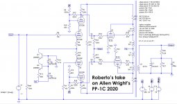
So, this is what I meant:
Local feedback on the cascoded PI, local feedback on the EL34, 43%UL connection, fixed bias.
B+ at 450V, 4k Raa for a quad of EL34 per channel (8k Raa per pair) using the cheap OPT Toroidy TTG-KT88PP ( TTG-KT88PP - Tube output transformer [4kOhm] 2xKT88 / 2x300B Push-pull or similar - Shop Toroidy.pl ).
This is what I get at 40 Wrms:
And this is what I get at 75 Wrms:
Local feedback on the cascoded PI, local feedback on the EL34, 43%UL connection, fixed bias.
B+ at 450V, 4k Raa for a quad of EL34 per channel (8k Raa per pair) using the cheap OPT Toroidy TTG-KT88PP ( TTG-KT88PP - Tube output transformer [4kOhm] 2xKT88 / 2x300B Push-pull or similar - Shop Toroidy.pl ).
This is what I get at 40 Wrms:
Code:
Harmonic	Frequency	 Fourier 	Normalized	 Phase  	Normalized
 Number 	  [Hz]   	Component	 Component	[degree]	Phase [deg]
    1   	1.000e+03	1.245e+01	1.000e+00	   -2.08°	    0.00°
    2   	2.000e+03	3.366e-03	2.704e-04	  -99.67°	  -97.59°
    3   	3.000e+03	1.201e-03	9.645e-05	  -34.60°	  -32.52°
    4   	4.000e+03	2.173e-04	1.745e-05	  172.16°	  174.24°
    5   	5.000e+03	8.081e-04	6.491e-05	  174.92°	  177.00°
    6   	6.000e+03	1.428e-04	1.147e-05	  179.61°	  181.69°
    7   	7.000e+03	9.675e-05	7.772e-06	 -178.56°	 -176.48°
    8   	8.000e+03	1.071e-04	8.600e-06	  179.71°	  181.79°
    9   	9.000e+03	9.624e-05	7.731e-06	  179.60°	  181.68°
Total Harmonic Distortion: 0.029542%(0.029614%)
And this is what I get at 75 Wrms:
Code:
Harmonic	Frequency	 Fourier 	Normalized	 Phase  	Normalized
 Number 	  [Hz]   	Component	 Component	[degree]	Phase [deg]
    1   	1.000e+03	2.432e+01	1.000e+00	   -2.07°	    0.00°
    2   	2.000e+03	1.268e-02	5.212e-04	  -96.47°	  -94.40°
    3   	3.000e+03	3.907e-01	1.607e-02	   -4.12°	   -2.05°
    4   	4.000e+03	8.601e-04	3.537e-05	 -111.21°	 -109.14°
    5   	5.000e+03	1.753e-01	7.207e-03	  174.70°	  176.77°
    6   	6.000e+03	1.207e-03	4.964e-05	 -113.89°	 -111.82°
    7   	7.000e+03	4.301e-02	1.768e-03	   -8.26°	   -6.20°
    8   	8.000e+03	1.845e-03	7.587e-05	   89.06°	   91.13°
    9   	9.000e+03	7.451e-03	3.064e-04	    1.88°	    3.95°
Total Harmonic Distortion: 1.770779%(1.772507%)
Attachments
Is this THD measured in real life or from a simulation?
The 40 Watt figures are quite impressive.
Regards, Gerrit
The 40 Watt figures are quite impressive.
Regards, Gerrit
Hi Zintolo,
I took your model, added the second pair of EL34, adjusted the transformer to 4k and used a much smaller time step to increase accuracy for THD analysis. Distortion at 40W is more like 0.4%, not 0.03%. Some observations:
-220k anode resistors driving 100k grid resistors doesn't really make sense
-You are running the ECC88s at very low current and missing out on the gm and reduced distortion available at higher currents
-The cascode output impedance is very high, and so there is significant drop in response at higher frequencies due to the output stage input capacitance
-The "Baby Huey" style of Schade feedback results in relatively high distortion, especially at higher outputs
-I don't think the anode to grid feedback in the top ECC88 is doing much except reducing gain, perhaps helping a bit with output impedance
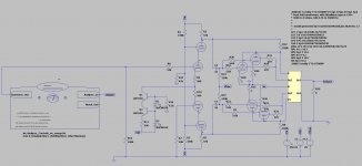
- The simulation indicates significantly better results by increasing total LTP current to about 8 mA, dropping the anode resistor value a lot to end up with with ~230V on the top anode, and connect it to B+, increasing output stage grid resistors as much as you can within the allowable limits, and adding a touch of normal Schade feedback with a large value resistor from the output stage anodes back to the cascode anodes. See attached schematic - sorry I can't paste the .asc file because it only works with my custom setup.
I took your model, added the second pair of EL34, adjusted the transformer to 4k and used a much smaller time step to increase accuracy for THD analysis. Distortion at 40W is more like 0.4%, not 0.03%. Some observations:
-220k anode resistors driving 100k grid resistors doesn't really make sense
-You are running the ECC88s at very low current and missing out on the gm and reduced distortion available at higher currents
-The cascode output impedance is very high, and so there is significant drop in response at higher frequencies due to the output stage input capacitance
-The "Baby Huey" style of Schade feedback results in relatively high distortion, especially at higher outputs
-I don't think the anode to grid feedback in the top ECC88 is doing much except reducing gain, perhaps helping a bit with output impedance
- The simulation indicates significantly better results by increasing total LTP current to about 8 mA, dropping the anode resistor value a lot to end up with with ~230V on the top anode, and connect it to B+, increasing output stage grid resistors as much as you can within the allowable limits, and adding a touch of normal Schade feedback with a large value resistor from the output stage anodes back to the cascode anodes. See attached schematic - sorry I can't paste the .asc file because it only works with my custom setup.
Attachments
Thanks Tikiroo,
can you please post the THD at 40 and 75 Wrms?
Just to understand if it worths building it or not.
Of course I'm, also looking for your and others' impressions about it.
Roberto
can you please post the THD at 40 and 75 Wrms?
Just to understand if it worths building it or not.
Of course I'm, also looking for your and others' impressions about it.
Roberto
Distortion results below. I adjusted my modified design to have the same overall gain as your original. At the 75W level my design is showing a third harmonic null at the expense of increased higher harmonics, which I don't like, but this is very loud!
Original 40W
h2: =0.0315032092506
h3: =0.409874872129
h4: =0.000354041077567
h5: =0.0226018076673
h6: =4.59094531546e-005
h7: =0.00441202309383
h8: =1.48431376653e-005
h9: =4.88507156465e-005
h10: =5.80079842587e-006
thd_percent: =0.411728430821
Original 75W
h2: =0.0268244677021
h3: =2.00424930184
h4: =0.00949697117794
h5: =0.665648411797
h6: =0.00068367372055
h7: =0.201484787807
h8: =0.00347975180635
h9: =0.0107504218798
h10: =0.00274185935496
thd_percent: =2.1217079445
Modified by Tikiroo 40W
h2: =0.00997468749244
h3: =0.259661197608
h4: =0.000434333355478
h5: =0.0132402618585
h6: =2.18364287534e-0 05
h7: =0.00314518374474
h8: =7.74868906295e-006
h9: =0.000572668165842
h10: =6.98257454794e-006
thd_percent: =0.260209811169
Modified by Tikiroo 75W
h2: =0.0198604882521
h3: =0.309708861062
h4: =0.00386727317228
h5: =0.416522374217
h6: =0.00129854131048
h7: =0.174987446959
h8: =0.000382866072871
h9: =0.0577160319939
h10: =3.88212608685e-005
thd_persent: =0.551156459533
How do you calculate your output power. For me 24Vp on 6ohms is 48W, how do you find 75W?So, this is what I meant:
Local feedback on the cascoded PI, local feedback on the EL34, 43%UL connection, fixed bias.
B+ at 450V, 4k Raa for a quad of EL34 per channel (8k Raa per pair) using the cheap OPT Toroidy TTG-KT88PP ( TTG-KT88PP - Tube output transformer [4kOhm] 2xKT88 / 2x300B Push-pull or similar - Shop Toroidy.pl ).
This is what I get at 40 Wrms:
Code:Harmonic Frequency Fourier Normalized Phase Normalized Number [Hz] Component Component [degree] Phase [deg] 1 1.000e+03 1.245e+01 1.000e+00 -2.08° 0.00° 2 2.000e+03 3.366e-03 2.704e-04 -99.67° -97.59° 3 3.000e+03 1.201e-03 9.645e-05 -34.60° -32.52° 4 4.000e+03 2.173e-04 1.745e-05 172.16° 174.24° 5 5.000e+03 8.081e-04 6.491e-05 174.92° 177.00° 6 6.000e+03 1.428e-04 1.147e-05 179.61° 181.69° 7 7.000e+03 9.675e-05 7.772e-06 -178.56° -176.48° 8 8.000e+03 1.071e-04 8.600e-06 179.71° 181.79° 9 9.000e+03 9.624e-05 7.731e-06 179.60° 181.68° Total Harmonic Distortion: 0.029542%(0.029614%)
And this is what I get at 75 Wrms:
Code:Harmonic Frequency Fourier Normalized Phase Normalized Number [Hz] Component Component [degree] Phase [deg] 1 1.000e+03 2.432e+01 1.000e+00 -2.07° 0.00° 2 2.000e+03 1.268e-02 5.212e-04 -96.47° -94.40° 3 3.000e+03 3.907e-01 1.607e-02 -4.12° -2.05° 4 4.000e+03 8.601e-04 3.537e-05 -111.21° -109.14° 5 5.000e+03 1.753e-01 7.207e-03 174.70° 176.77° 6 6.000e+03 1.207e-03 4.964e-05 -113.89° -111.82° 7 7.000e+03 4.301e-02 1.768e-03 -8.26° -6.20° 8 8.000e+03 1.845e-03 7.587e-05 89.06° 91.13° 9 9.000e+03 7.451e-03 3.064e-04 1.88° 3.95° Total Harmonic Distortion: 1.770779%(1.772507%)
With 12.45Vp on 6.25 ohm is 12.4w, how 40w?
Last edited:
For 450V B+ swinging down to 60V, Vp is 390V = 276V rms for each half winding. = 552V rms AA into 4k primary = 76W.

Zintolo posted a schematic with a single pair of el34 but his figures were for 2 pairs. With a single pair you are correct 🙂
Thanks kokoriantz,
Please note that 4k Raa is for a quartet of EL34, not a pair.
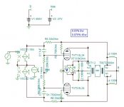
Looking at the images you posted, best result you have got is with 450V B+, 35% UL, 33k on 200k anode to grid feedback, 6k6 Raa (3k3 per quartet) with 750 Ohm screen stoppers.
830Vpp means you reach 35 V at 250 mA. Are those THD numbers still valid with grid stoppers in? They are very impressive.
I'm wondering if, but then in a dedicated thread because here would be off topic, Rod Coleman's shunt cascode driver ( Shunt Cascode Power Valve Driver ) could be a better solution for this power amp.
As for the output transformer, Toroidy makes them up to 80 Wrms, so no way to use a quartet of EL34 having very clean 90 Wrms on paper. The closest one for a pair of EL34 is this one ( TTG-CFB6600PP - Tube output CFB transformer [6,6kOhm] Cathode Feedback Push-pull - Shop Toroidy.pl ) without using the CFB part.
Please note that 4k Raa is for a quartet of EL34, not a pair.
Looking at the images you posted, best result you have got is with 450V B+, 35% UL, 33k on 200k anode to grid feedback, 6k6 Raa (3k3 per quartet) with 750 Ohm screen stoppers.
830Vpp means you reach 35 V at 250 mA. Are those THD numbers still valid with grid stoppers in? They are very impressive.
I'm wondering if, but then in a dedicated thread because here would be off topic, Rod Coleman's shunt cascode driver ( Shunt Cascode Power Valve Driver ) could be a better solution for this power amp.
As for the output transformer, Toroidy makes them up to 80 Wrms, so no way to use a quartet of EL34 having very clean 90 Wrms on paper. The closest one for a pair of EL34 is this one ( TTG-CFB6600PP - Tube output CFB transformer [6,6kOhm] Cathode Feedback Push-pull - Shop Toroidy.pl ) without using the CFB part.
Zintolo posted a schematic with a single pair of el34 but his figures were for 2 pairs. With a single pair you are correct 🙂
Thanks tikiroo, my fault indeed not having posted the right schematic since the beginning. I'd still prefer a quartet of EL34 per channel, but I've never used an amp with the OPT as a bottleneck, considering that part of the feedback is given by the OPT.
The feedback is screen to grid. The UL is 40%. I took 10mS input tubes as 6H30 initially used. The cascode can be high voltage transistor. With 1k grid stopper nothing changes.
Thanks kokoriantz,
I will try that configuration this evening.
You suggest a PI with half 6H30 on the bottom and an high voltage transistor on top, on each side?
Is it better to scale the feedback and apply it from the anodes, or it is ininfluent in reality?
I will try that configuration this evening.
You suggest a PI with half 6H30 on the bottom and an high voltage transistor on top, on each side?
Is it better to scale the feedback and apply it from the anodes, or it is ininfluent in reality?
This configuration has been done more than a decade ago on this forum, he transformed the ST70 but driven by triodes. I will try by anode and ac reducing mutual resistor. The original Allen Wright I think uses the 6H30, this expensive Russian tube has extraordinary constant u and runs at low voltage. I once tried out using MJE1300X high voltage transistor in cascode, it worked well.
I tried by anode with 47k feedback, the sensitivity is lower but 2Vp is sufficient to saturate. It doesn't need mutual resistor. The distortion at 43W is 0.04%. The DF is always 7.
I tried by anode with 47k feedback, the sensitivity is lower but 2Vp is sufficient to saturate. It doesn't need mutual resistor. The distortion at 43W is 0.04%. The DF is always 7.
Last edited:
Thanks once more kokoriantz!
I would say that I'll open a dedicated thread with that new option, as IMHO it will divert too much from this topic.
I would say that I'll open a dedicated thread with that new option, as IMHO it will divert too much from this topic.
No , I am wrong with anode feedback. The cascode is biased 7 ma to output across 39k about +/- 270 volt on screen to become about +/-700V on anode. Already the bias was wrong it needed 9ma bias for full +/-800v. With anode feedback 56k needs +/-17ma for +/-800v, but biased 18ma the voltage drop leaves nothing for the driver.
- Home
- Amplifiers
- Tubes / Valves
- Question re Allen Wright PP-1cs