Long time ago, EC8010 suggested that : "a pair of PCF80 would make a very nice line stage/buffer. Use the triode section as a cathode follower, and sit it on the pentode section used as a constant current sink. Use a 300mA DC constant current regulated heater supply, and you'd have something with performance completely out of proportion to price."
I've a dozen of those tubes, transformers, caps, resistors and so on. Cost would we be near zero 🙂
For the cathode follower, ok, I found some articles explaining me how to design them. However, I've some problems to find a simple ccs using a pentode. Could someone link me to one ?
PS: the pcf80 : http://www.r-type.org/exhib/aaa0252.htm
You might poke around Gary Pimm's website; he's the ultimate CCS fetishist. There's also some very detailed design stuff in "Valve Amplifiers."
Gary Pimms Circuits are probably the best solution.
However a Mu Follower will be a close approximation to a CCS. If you have plenty of voltage to burn then the current sensing resistor under the pentode can be made large which will stiffen the CCS properties. You will have to consider this more as a SEPP stage than a true CCS. I used this approach in building a Parafeed SET amp which has worked really well.
Shoog
Let's see if I can give you a good description. At least for now, I do schematics by hand with pencil and paper.
You stack the triode on top of the pentode (triode cathode connected to pentode anode). Connect triode anode to B+. Connect pentode g2 to B+ via 1 Megohm resistor. Connect pentode g2 to pentode cathode via a small cap. Ground pentode g1. Connect pentode cathode to ground via series combo of variable resistor and 10 Ohm fixed part. Use Ohm's Law to set the current by measuring the voltage drop across the 10 Ohm fixed resistance. I like battery bias; so, connect + side of 6 V. Lithium device to triode cathode. Connect - side of battery to 1 Megohm grid leak resistor. Connect grid leak resistor to triode grid. Cap. couple triode grid to wiper of volume control. Cap. couple (4.7 muF.) triode cathode to O/P jack. Wire 1 Megohm resistor across O/P jack.
You stack the triode on top of the pentode (triode cathode connected to pentode anode). Connect triode anode to B+. Connect pentode g2 to B+ via 1 Megohm resistor. Connect pentode g2 to pentode cathode via a small cap. Ground pentode g1. Connect pentode cathode to ground via series combo of variable resistor and 10 Ohm fixed part. Use Ohm's Law to set the current by measuring the voltage drop across the 10 Ohm fixed resistance. I like battery bias; so, connect + side of 6 V. Lithium device to triode cathode. Connect - side of battery to 1 Megohm grid leak resistor. Connect grid leak resistor to triode grid. Cap. couple triode grid to wiper of volume control. Cap. couple (4.7 muF.) triode cathode to O/P jack. Wire 1 Megohm resistor across O/P jack.

"You stack the triode on top of the pentode (triode cathode connected to pentode anode). Connect triode anode to B+. Connect pentode g2 to B+ via 1 Megohm resistor. Connect pentode g2 to pentode cathode via a small cap. Ground pentode g1. Connect pentode cathode to ground via series combo of variable resistor and 10 Ohm fixed part. Use Ohm's Law to set the current by measuring the voltage drop across the 10 Ohm fixed resistance. I like battery bias; so, connect + side of 6 V. Lithium device to triode cathode. Connect - side of battery to 1 Megohm grid leak resistor. Connect grid leak resistor to triode grid. Cap. couple triode grid to wiper of volume control. Cap. couple (4.7 muF.) triode cathode to O/P jack. Wire 1 Megohm resistor across O/P jack."
You'll have to do that as a schematic before I can follow it.
In my use of a Pentode as a CCS it went in the endode of the triode rather than the cathode.
Shoog
You'll have to do that as a schematic before I can follow it.
In my use of a Pentode as a CCS it went in the endode of the triode rather than the cathode.
Shoog
In my use of a Pentode as a CCS it went in the endode of the triode rather than the cathode.
That's correct for a common cathode voltage gain block. The thread's initiator asked for a CCS (sink) loaded cathode follower.
FWIW, I envisage the use of the PCF80 in this manner working WELL. It should be HIGHLY linear and the O/P impedance will be approx. 200 Ohms. Even the NASTY IHF "standard" 10 KOhm load should be handled with ease.
"That's correct for a common cathode voltage gain block. The thread's initiator asked for a CCS (sink) loaded cathode follower."
Thanks for correcting me on that one.
Shoog
Thanks for correcting me on that one.
Shoog
00940 said:Long time ago, EC8010 suggested that : "a pair of PCF80 would make a very nice line stage/buffer. Use the triode section as a cathode follower, and sit it on the pentode section used as a constant current sink. Use a 300mA DC constant current regulated heater supply, and you'd have something with performance completely out of proportion to price."
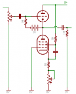
Sorry about the delay (took me a while to find an envelope to draw it on). Here it is:
Attachments
I would do it the other way. Pentode as the signal input tube. Triode's cathode to negative rail through the current setting R. Triode's grid to the negative rail.
The triode will be a fine load for the pentode's cathode, and the pentode's plate will be more tolerant of B+ ripple. Pentode's anode to B+, g2 to one end of a 100k resistor, and B+ to the other. 0.5 uF to 1 uF cap between g2 and the pentode's cathode.
cheers,
Douglas
The triode will be a fine load for the pentode's cathode, and the pentode's plate will be more tolerant of B+ ripple. Pentode's anode to B+, g2 to one end of a 100k resistor, and B+ to the other. 0.5 uF to 1 uF cap between g2 and the pentode's cathode.
cheers,
Douglas
That's not as advantageous as it might seem. The ripple on a triode plate will be attenuated in the CF output by a factor of mu (20 in this case). Whatever ripple is present on the screen will be passed unattenuated. Now, you do have an RC rolloff, but with the values you give, the attenuation isn't any better than mu anyway. Sure, you could go up another factor of 10 on the cap, but that increases size and cost.
It's pretty easy (see my preamp article) to get the ripple down to ridiculously low levels, so why not put the big cap toward that end? That way, one can take advantage of the much superior CCS characteristics of a pentode plate.
It's pretty easy (see my preamp article) to get the ripple down to ridiculously low levels, so why not put the big cap toward that end? That way, one can take advantage of the much superior CCS characteristics of a pentode plate.
ALright, I pulled the sheet on this beastie. It isn't a very good tube for the use you all propose. Two EF184 will cost $5USD and they have 15 mA/V transconductance. That amounts to ~50R output Z for a cathode follower. They have 90kOhm plate Z so they make fine sink-CCS too.
If I were going to the trouble of cutting a bunch of holes and assembling a proper power supply, that's the way I'd do it. Or one could take Sy's route and rig the input valve as a triode...
cheers,
Douglas
If I were going to the trouble of cutting a bunch of holes and assembling a proper power supply, that's the way I'd do it. Or one could take Sy's route and rig the input valve as a triode...
cheers,
Douglas
Bandersnatch said:Two EF184 will cost $5USD and they have 15 mA/V transconductance. That amounts to ~50R output Z for a cathode follower. They have 90kOhm plate Z so they make fine sink-CCS too.
Agreed, EF184 is a very nice valve indeed and if you're going to gp to the trouble of nice metalwork specifically for a cathode follower line stage, then it's a much better choice, However, if you need a triode cathode follower with pentode CCS in an existing piece of equipment and have room to bash a single hole with not much HT, then the PCF80 could work very nicely.
I take the point about ripple rejection and g2. My back of the envelope sketch used the minimum voltage possible and the curves were for g2 = 170V, so I just took g2 to the HT. A better idea would be to do some tests with a lower g2, allowing RC smoothing to g2.
and the sad thing is those ECF80 come at 7 per Tektronix 502, so I have a small sack of them. All European Amperex. The pentode section is really a 3-grid pentode, and the triode section is like twice the gm of a 6SN7.
I would suggest an even more complex arrangement, involving some ~100V voltage references and stack the pentode on top of the triode, cascode style. This still leaves one with the trouble of a cathode sink...
cheers,
Douglas
I would suggest an even more complex arrangement, involving some ~100V voltage references and stack the pentode on top of the triode, cascode style. This still leaves one with the trouble of a cathode sink...
cheers,
Douglas
00940 mail
Sorry this is off topic.....
00940
Dear Sir - I could not email You - this is why
I am sending You this email..... Do You know where to find RKV headphone schematic?
Best regards
sunny
Sorry this is off topic.....
00940
Dear Sir - I could not email You - this is why
I am sending You this email..... Do You know where to find RKV headphone schematic?
Best regards
sunny
Quick in - quick out ....
I've had Pete Millett's original article in AudioXpress (low mu triode CSS preamp) for breakfast (well litterature to my tea and cereals) for severeal days, and though the design is flawless I still wanted to make some changes.
The 6AS7-EL34-duo is a bit too strong and consumes a little too much current for the heaters so I started thinking of other duos that could do the trick but with less heat. What I came up with was the 12B4A-triode and an EL84, or possible an 6AQ5 as CSS. Or using the Russian 6N6P (6H30P, 5687, E182CC) as triode and the 6AQ5/6BQ5 for pentode.
Would that be reasonable if you still want some current capability?
Hello, I'd like to try this little project as I have a couple of spare PCF80.
I have a couple of questions about the schematics posted:
- is there any resistor between B+ and pentode G2?
- is there any resistor between triode cathode and pentode anode?
Plus: what would be a good choice for a B+ power supply in this case? I have seen several designs (i.e.: A New High-Voltage Regulator) but still undecided on which to choose.
Thanks in advance!
- Status
- Not open for further replies.
- Home
- Amplifiers
- Tubes / Valves
- Question : pentode ccs schematic ?