hello,
Some time ago, i assembled this preamp
SUQIYA Pre biliary PRT10A tube preamplifier finished board refer to Hetian Mao's circuit|Amplifier| - AliExpress
I use it with a Topping D90 DAC and the L12-2
the thing is that I get a lot of saturation unless I reduce the PC output volume ti the DAC.
On my integrated amp I can set the pc output to MAX do I guess the issue is the preamp.
I have a volume pot on the input of the preamp but even set de minimum the saturation is still here unless I reduce the output of the PC.
If anyone has an idea, I am ll ears.
Thanks
You are adding a completely unnecessary high gain preamp between your DAC (which probably puts out 1 or 2V RMS) and your power amp which is probably driven by 1V RMS or so.
Either the Preamp clips or, more probably, its 30-40V RS (or more) SMASHES your Power Amp input.
Best option is not to use it, of course.
Not needed, it can only damage your sound.
It supposedly adds "Marantz Sound" ......
If that´s your goal, then also build the Marantz Tube Power Stage, in full.
Either the Preamp clips or, more probably, its 30-40V RS (or more) SMASHES your Power Amp input.
Best option is not to use it, of course.
Not needed, it can only damage your sound.
Indeed!!!! 😱two-stage common cathode scale amplification, and the output stage uses the SRPP method
It supposedly adds "Marantz Sound" ......
If that´s your goal, then also build the Marantz Tube Power Stage, in full.
Yes. 12AT7 (ECC81) have amplification factor of 70. ust output stage in that SRPP topology have gain close to the mju of the tube.
So You can count that total gain stage is 60 times that is for 1V input 60V output of the preamp going in the amplifier input stage.
.
this device, as is, could be of use only in the analog stage of some current output dac to amplify low voltage after R-IV DAC out?
So You can count that total gain stage is 60 times that is for 1V input 60V output of the preamp going in the amplifier input stage.
.
this device, as is, could be of use only in the analog stage of some current output dac to amplify low voltage after R-IV DAC out?
Last edited:
Hello all.
Thanks for your answers.
But my main goal was not to achiev a marantz sound or add gain. I was just hoping for a tubish sound.
I am a noob and didn't expect such gain from it.
I thought preamps helped with sound stage,definitions and so on but not add gain to the loop.
So it seems it will go staight tu a cupboard 🙁
Thanks again everyone for answering my question.
Last edited:
Ok, you should have added a Tube Buffer instead, with typically a gain of 1
Just as an experiment, you may try adding an attenuator, a 2 resistor voltage divider at the output, to tame excess output signal level, not too late to try it.
Say 50X: 10k series + 220 ohm to ground.
Driven that hard, that preamp will add a lot of colour .... maybe too much.
Just as an experiment, you may try adding an attenuator, a 2 resistor voltage divider at the output, to tame excess output signal level, not too late to try it.
Say 50X: 10k series + 220 ohm to ground.
Driven that hard, that preamp will add a lot of colour .... maybe too much.
Last edited:
.....I have a volume pot on the input of the preamp but even set de minimum the saturation is still here...
The volume pot should go to ZERO. Why doesn't it? (I don't see it on the preamp ad, so I don't know how yours is wired.)
The volume pot should go to ZERO. Why doesn't it? (I don't see it on the preamp ad, so I don't know how yours is wired.)
In deed there is no pot on the ad but I put a 100k on the input.
Nothing between the preamp and the power amp.
Well it's quite simple, RCA input to 100k pot, then 100k pot to input of the PCB, and PCB to output RCA.
@JMFahey ok, I will give it a go.
It is DIY, I will check in my components if I have these parts.
Or, I have a relay volume control. Can I put that on the output instead?
Thanks
Maybe, but we don´t know schematics, specs, nothing, while 2 plain resistors are easier and predictable..
I suggest you buy a resistor and capacitor kit (or write down your own) with generic, multipurpose values, say 10 ohm, 50, 100, 220 ... up to 1M, a few capacitors from 100pF to .1uF , etc. , say 10 resistors each value , 5 capacitors each,etc, cost is very low, so you have them on hand for experiments or tweaking without ordering cheap parts every time you have an idea or doubt , waiting for a week or more, and paying $10 freight on $1 worth of parts.
I bet there must be such generic parts kits for experimenters available.
Very practical and no need to order *all* values available, for example if you need 330pF you use 100 and 220 in parallel, etc.
Something like this.
It´s a monster kit, including even speakers, but use the standard components values as a guide.
O the ones shown under it:
https://www.amazon.com/Electronic-Component-Assortment-Capacitors-Transistors/dp/B073TKQNL3
Well it's quite simple, RCA input to 100k pot, then 100k pot to input of the PCB, and PCB to output RCA.
No grounding of that pot?
No grounding of that pot?
Nope, only the negative wire. My case is grounded tough.
I will check if the pot benefits from it. Of not I will pull a wire.
Also forgot to mention, my input is a relays input selectors. Powdered by 14v DC. Maybe I should also try a direct connection
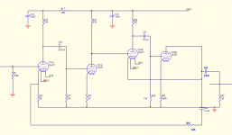
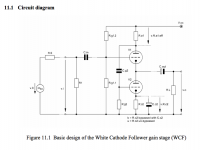
I think there is no SRPP at all it is the diferent. 2 gain stages at input, extremly high gain aboit 30x30 times, or more, and buffer at the output. buffer is white cathode follower.
many local feedbacks and one flobal FB.
.
simple way to adopt is to use only white cathode follower.
2 resistors to add and some existing values to change. And cut out global feedback
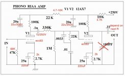
input 2 x tube have to be removed. Actually You can build RIAA preamp with that input stage if You put between some all in one riaa network
many local feedbacks and one flobal FB.
.
simple way to adopt is to use only white cathode follower.
2 resistors to add and some existing values to change. And cut out global feedback
input 2 x tube have to be removed. Actually You can build RIAA preamp with that input stage if You put between some all in one riaa network
Attachments

Last edited:
I think there is no SRPP at all it is the diferent. 2 gain stages at input, extremly high gain aboit 30x30 times, or more, and buffer at the output. buffer is white cathode follower.
many local feedbacks and one flobal FB.
.
simple way to adopt is to use only white cathode follower.
2 resistors to add and some existing values to change. And cut out global feedback
input 2 x tube have to be removed. Actually You can build RIAA preamp with that input stage if You put between some all in one riaa network
Wow, thanks, as a noob I will show this to my friend who is an electronic engineer to help guide me in this process.
RIAA preamp would be a nice way to recyle it in deed.
1) thanks for the schematic.
2) I also find the output stage WEIRD, certainly not what I expected from the SRPP label
3) circuit has TONS of open loop gain, then SMASHES it with heavy negative feedback, it´s reduced to (22/2)+1=12X
4) it will NOT give you "Tube Sound or Flavour" at all, unless overdriven,which is not the case.
It has very very low distortion, very flat frequency response, low output impedance, closer to an Op Amp stage than to a classic tube stage.
IF this is a derivation of Golden Era Marantz circuits, not surprised, they were trying to improve, linearize Preamps (and Power Amps), not build "Effects Boxes".
The ideal was "wires with gain".
Only problem you are having is 12X increased signal overdrives your power amp, I still suggest a fixed attenuator at the output but now 10k>1k which will be perfect.
I do not suggest neurosurgery for majpr changes on the existing preamp because it´s built on a PCB , you have what you have, it will be more complicated than building a new one from scratch.
Keep the preamp as-is , add the attenuator to insert it in your Audio chain OR use it, 12X gain,no attenuation, to drive your Power Amp from a Phone or MP3 player or similar "weak" sound source, their Earphone out typically puts out meager 100 to 200 mV RMS
1) thanks for the schematic.
2) I also find the output stage WEIRD, certainly not what I expected from the SRPP label
3) circuit has TONS of open loop gain, then SMASHES it with heavy negative feedback, it´s reduced to (22/2)+1=12X
4) it will NOT give you "Tube Sound or Flavour" at all, unless overdriven,which is not the case.
It has very very low distortion, very flat frequency response, low output impedance, closer to an Op Amp stage than to a classic tube stage.
IF this is a derivation of Golden Era Marantz circuits, not surprised, they were trying to improve, linearize Preamps (and Power Amps), not build "Effects Boxes".
The ideal was "wires with gain".
Only problem you are having is 12X increased signal overdrives your power amp, I still suggest a fixed attenuator at the output but now 10k>1k which will be perfect.
I do not suggest neurosurgery for majpr changes on the existing preamp because it´s built on a PCB , you have what you have, it will be more complicated than building a new one from scratch.
Keep the preamp as-is , add the attenuator to insert it in your Audio chain OR use it, 12X gain,no attenuation, to drive your Power Amp from a Phone or MP3 player or similar "weak" sound source, their Earphone out typically puts out meager 100 to 200 mV RMS
ok I see, now, this explains why I have to reduce the output of the PC then. Well, I don't use weak sound sources except maybe my phono stage that ouputs something like 300mv.
I will go for the attenuator mode.
Thank
About the pasive riaa net refer to this high impedance all in one net.
(or other riaa high impedance all in one pasive net)
But with change of some in circuit values.
Change input tube to ECC83 (12AX7)
RIAA Network Phono Amp | TTRadio
(or other riaa high impedance all in one pasive net)
But with change of some in circuit values.
Change input tube to ECC83 (12AX7)
RIAA Network Phono Amp | TTRadio
Attachments
- Home
- Source & Line
- Analog Line Level
- Question on 12at7 preamp distortion