Hai everybody! Have a question for you experts out there.
Yesterday I completed a 4 channel version of Anthony Holton's N-channel Amplifier. Please don't get confused. This is the one that uses N-type Mosfets only in the output stage and uses an LM317T and IRF610 Mosfet to set the bias.
I used IRFP460 outputs on two boards and IRFP250N on two of the others. In the case of the IRFP460 boards, I was not able to set the bias beyond 180mA (60mA per device at +-70volt rails). Beyond 180mA, turning the pot reduced the bias current gradually. So I left it at 180mA.
In the case of the IRFP250Ns, I set the bias to 240mA (80mA per device at +-70volt rails). The bias could go higher but I set it at this point).
First question; Why this phenomenon? Does it have anything to do with N types verses the plain types or is it some other parameter?
The on load rails were at 69.7 volts and I assume that the off load voltage should have been over 72 volts. The transformer was a 1.1KVA toroidal and total capacitance was 60,000uF per rail.
I connected one channel using 460s and another using 250Ns to Jamo System II speakers and a CD player for source. There was a discernable difference in the character of the sound of each channel. Overall, the sound was magical.
After about 20 minutes, the channel using IRFP250s gave up the ghost. There was a flash and the output devices, Gate and Source resistors charred.
Reasons I could surmise were that the off load voltage was too high and heat sink temperature could have been a bit too high. (Although I should say that there was sufficient heatsink and a fan to cool it).
Any other reasons for the IRFP 460s surviving and the IRFP250Ns burning, apart from the difference in the bias setting?
Comments and analysis welcome for the benefit of all who may be attempting to build this amp.
Thanks in advance.
For the bias setting I would guess that this is normal considering the different Vgs characteristics for the two different FETs. IRFP460 has some 3-5 V of Vgs and IRFP250 has some 2-4. Typically that would mean, AFAIK, that the bias circuitry would be able to bias them differently.
As far the smoke I offer no info...
Where did you get the boards?
As far the smoke I offer no info...
Where did you get the boards?
Hi Sam
Was the heatsink burning hot after it blew? If it was, the thermal controller was either not working properly or not connected properly to the heatsink. The IRF types are like bipolars, they must have thermal tracking.
If the heatsink was cold, chances are high frq oscillation (ie. unstable). Check the output with a scope.
In my sym-amps I have had 5-6 failures like you describe, and I think they were all caused by thermal runaway. This amp seems really sensitive to the bias and temperature. The key is to bolt the bias controlling transistor right through with the hottest of the output stage devices. You could consider using a bipolar transistor there instead of an IRF610, since BJTs have higher temperature coefficient (they'll cause a slight overcompensation reducing the bias with increasing temperature). The sym amp has a BD139 there, I did try the IRF610 but the transistors tended to heat up too much over time.
OK. I need some new info.
I haven't done much with MOSFETs but I thought one of the advantages was negative thermal response, hence runnaway is not possible and themal feedback not needed.
Am I misinformed? Regarfing all MOSFETs? Regarding only some? If some- which are which?
Or - is the BJT drivers "upstream" from the MOSFETs that are the problem? that are the culprits?
Ghost
It is very nice expression , but I mean, that mistake is somewhere else. If circuit diagram of your amplifier is the same as on Holton's pages, and I mean that probably is, mistake is not in choise of types fets, but the real cause circuit diagram. Because this amplifier have not protection zener diodes in gates "bottom" fets, if goes to the overload ( or clipping, if you can ), voltage on theirs gates in this case will be higher then 20 V ( typical Ugsmax is +/- 20 V ), gate will "break true" and fet is destroyed. If you cannot try it again, connect to the gates of fets zener diodes ( parallel to G and S ) approximately 10 V / 500 mW in series with normal diodes 1N4148, which stoped your problems
It is very nice expression
, but I mean, that mistake is somewhere else. If circuit diagram of your amplifier is the same as on Holton's pages, and I mean that probably is, mistake is not in choise of types fets, but the real cause circuit diagram. Because this amplifier have not protection zener diodes in gates "bottom" fets, if goes to the overload ( or clipping, if you can ), voltage on theirs gates in this case will be higher then 20 V ( typical Ugsmax is +/- 20 V ), gate will "break true" and fet is destroyed. If you cannot try it again, connect to the gates of fets zener diodes ( parallel to G and S ) approximately 10 V / 500 mW in series with normal diodes 1N4148, which stoped your problems Originally posted by sam9
I haven't done much with MOSFETs but I thought one of the advantages was negative thermal response, hence runnaway is not possible and themal feedback not needed.
So far, only the lateral mosfets from Hitachi (like 2sk1058/2sj162) do not need thermal control. IRF, IRFP are like bipolars......they are not immune to thermal runaway.
I'm pretty sure IRFP240s and 9240s have a negative Vgs temperature coefficient leading to a natural increase in bias current with temperature. But this temperature coefficient is not as strong as the Vbe change of a BJT. I used a IRF610 as the 'sensor' transistor and the bias was slightly undercompensated. With a BD139 instead it is slightly overcompensated which is much safer.
Re: Is the temp co-efficient positive or negative?
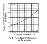
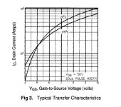
That picture shows a positive temperature coefficient of Rds_on - i.e., increasing temperature increases Rds_on as you can plainly see. The picture next to it is the important one (in the datasheet I've got), where you can see that drain current has a positive tempco, i.e. for the same Vgs, increasing temperature increases drain current (you could also say Vgs has a negative tempco, i.e. it decreases with increasing temp and a constant Id). It is not until above 1.6A or thereabouts that tempco becomes negative, or drain current decreases with increasing temp for a constant Vgs. Source resistors can help counteract this tendency to some degree, but you'd probably still want a Vbe or Vgs multiplier or other temp sensing circuit.
That picture shows a positive temperature coefficient of Rds_on - i.e., increasing temperature increases Rds_on as you can plainly see. The picture next to it is the important one (in the datasheet I've got), where you can see that drain current has a positive tempco, i.e. for the same Vgs, increasing temperature increases drain current (you could also say Vgs has a negative tempco, i.e. it decreases with increasing temp and a constant Id). It is not until above 1.6A or thereabouts that tempco becomes negative, or drain current decreases with increasing temp for a constant Vgs. Source resistors can help counteract this tendency to some degree, but you'd probably still want a Vbe or Vgs multiplier or other temp sensing circuit.
millwood said:this is from irf540 datasheet.
Is the temp co-efficient positive or negative? Anyone having a similar chart for the Hitachis?
Unfortunately the positive temp.co-efficient (tce) of the RdsON has no any relation to Vgs. The IRF540 has negative tce to Vgs. This means that You have to make some compensation to keep the bias constant
Check out:http://www.irf.com/product-info/datasheets/data/irf540.pdf
IF You see the Fig3., You can see that under 5V, the Vgs is decrease as the temperature increase.
So in typical application the Vgs is around 3V for 100mA bias.
Sajti
Re: Re: Is the temp co-efficient positive or negative?
Ooppsss I late a bit 🙂
Sajti
piertr said:That picture shows a positive temperature coefficient of Rds_on - i.e., increasing temperature increases Rds_on as you can plainly see. The picture next to it is the important one (in the datasheet I've got), where you can see that drain current has a positive tempco, i.e. for the same Vgs, increasing temperature increases drain current (you could also say Vgs has a negative tempco, i.e. it decreases with increasing temp and a constant Id). It is not until above 1.6A or thereabouts that tempco becomes negative, or drain current decreases with increasing temp for a constant Vgs. Source resistors can help counteract this tendency to some degree, but you'd probably still want a Vbe or Vgs multiplier or other temp sensing circuit.
Ooppsss I late a bit 🙂
Sajti
Re: Re: Is the temp co-efficient positive or negative?
isn't that the same thing that the Hitachis do?
I would agree with the above. apparently, the transition takes place at much lower current level with the Hitachis (200ma per Sloan). BTW, did you mean 16amp?
I included a Vgs/Id chart below. One thing that really surprised me is that the high level of current the devices can take. In my experience with IRFs, I haven't been able to blow up anyone, even short circuiting the output. So I am not as convinced as others that those devices behave like BJTs.
Does anyone have similar charts for the Hitachis?
piertr said:That picture shows a positive temperature coefficient of Rds_on - i.e., increasing temperature increases Rds_on as you can plainly see.
isn't that the same thing that the Hitachis do?
piertr said:The picture next to it is the important one (in the datasheet I've got), where you can see that drain current has a positive tempco, i.e. for the same Vgs, increasing temperature increases drain current (you could also say Vgs has a negative tempco, i.e. it decreases with increasing temp and a constant Id). It is not until above 1.6A or thereabouts that tempco becomes negative, or drain current decreases with increasing temp for a constant Vgs. Source resistors can help counteract this tendency to some degree, but you'd probably still want a Vbe or Vgs multiplier or other temp sensing circuit.
I would agree with the above. apparently, the transition takes place at much lower current level with the Hitachis (200ma per Sloan). BTW, did you mean 16amp?
I included a Vgs/Id chart below. One thing that really surprised me is that the high level of current the devices can take. In my experience with IRFs, I haven't been able to blow up anyone, even short circuiting the output. So I am not as convinced as others that those devices behave like BJTs.
Does anyone have similar charts for the Hitachis?
Attachments
Would that be 16 Amps?
Yes, 16A (or thereabouts). Sorry, my mistake. (Can't seem to edit my post. Ahh, different IP means no edit post option...)
Yes, 16A (or thereabouts). Sorry, my mistake. (Can't seem to edit my post. Ahh, different IP means no edit post option...)
Re: Would that be 16 Amps?
Or 30 minutes has past....piertr said:(Can't seem to edit my post. Ahh, different IP means no edit post option...)
16 amps drain current before we get a positive temperature coefficient? No wonder we need a good Vbe multiplier. I think you can draw much more than that in a thermal runaway situation but by then it is too late. 🙂 (Maybe poly-switches[?] would be a good idea here.)
Also the IRF devices I am using seem to have a strong "knee" in the drain current vs. Vgs curve. Because of this they have to be matched closely or 1-2 devices hog most of the current. And if I try to increase the bias, most of that increase goes into a couple of transistors (not helping things), on one channel which isn't so well matched. It has 0.03 volt differences in Vgs at 100mA. The other's within 0.01 volts and it's fine.
Also the IRF devices I am using seem to have a strong "knee" in the drain current vs. Vgs curve. Because of this they have to be matched closely or 1-2 devices hog most of the current. And if I try to increase the bias, most of that increase goes into a couple of transistors (not helping things), on one channel which isn't so well matched. It has 0.03 volt differences in Vgs at 100mA. The other's within 0.01 volts and it's fine.
I do not have a scope to check for oscillations. However, I do not think it was oscillations that caused it.
Yes the heatsink was hot, the Gate resistors were charred and some of the Source resistors were also burnt.
The Gates of both banks of outputs are protected with 9.1V zeners, but not with anti-parallel IN4148s. That is how Anthony has shown the schematic.
The IRF610 is mounted atop one of the output devices and thermal contact is not at all a problem. Thermal compensation could be the problem. Perhaps, I will go back to BD681 as proposed by Anthony in his original schematic before updates of the N-channel amp were published.
This is the third occasion in which I have lost IRFP250N outputs. However, IRFP460s survived in the same situation, albeit with slightly lower bias.
Could the +-70volt rails be too high? Or is it thermal under-compensation due to the use of IRF610 rather than a BJT?
- Status
- Not open for further replies.
- Home
- Amplifiers
- Solid State
- Question - Biasing different types of Mosfets