Question regarding (some) DC current in push-pull output transformers:
I’m designing a pure class-A, push-pull amplifier using 6EM7 tubes. Each channel will have a differential pair with an LM334 at the tail RC-coupled to the pure class-A output stage using the power triodes. Being that these are old TV tubes, I can’t buy matched pairs, and I don’t have a tube tester. In fact, I already scored a 5-pack carton of NOS GE coin-base 6EM7s.
I know that pure class A is very forgiving of mismatched tubes (for example, the hypothetical PP circuit in the Radiotron Handbook uses a 2a3 opposite a 45, and the resulting circuit has only 5% 2nd-order harmonic distortion). I am concerned, however, about DC current in the output transformer. I know that DC current can reduce the primary inductance of a PP transformer, and cause distortion in the bass. But, I have also read about people building single-ended triode amps using push-pull transformers, and the amps work pretty well, so long as the standing current isn’t too great (35mA through a big H.H. Scott output transformer with a 45 single-ended triode amp, for example).
So — I know that any DC current in a push-pull transformer is theoretically bad because there’s no air gap, and the transformer might saturate too early. But, how bad is a little DC offset, in the real world? If I my amp puts out 7W (designed for 40mA idle current per tube) but uses the 10W (40Hz-18kHz, 1.6lbs) Edcor transformers, will the amp sound bad if there’s 5mA of idle current? 10mA? Can a normal E-I transformer handle this much slop?
I’m considering using Blumein’s “garter” circuit to force the output tubes into idle balance, but this would be complicated, and require a higher B+. Is it worth this effort to force the output tubes into balance? Or should I just use a shared resistor for both tubes, as I originally wanted?
This is a question for the maker of the output transformer you plan to use. Ask them how much imbalance can be tolerated by the specific transformer without seriously degrading the transformer performance. 10% imbalance at the rated current is not too atypical imle for a good transformer. Some makers publish the acceptable level of imbalance in their specifications.
Transformers vary in their tolerance of unbalanced DC. Hi-fi transformers generally have no gap to get the most inductance. PA and organ transformers generally have cores stacked in sections (like 4 in one direction, 4 the other etc.) which effectively gives a small gap, and allows a bit more imbalance. Doesn't hurt that saves labor in assembly...
Bass will be affected first if there's imbalance. Put a 10 Ohm resistor in each cathode for a current sample and you can select tubes with the best balance.
Bass will be affected first if there's imbalance. Put a 10 Ohm resistor in each cathode for a current sample and you can select tubes with the best balance.
For me no tolerance is acceptable. Every mA of DC robs the transformer of inductance and hence bass response. I always design for zero DC and generally get to within a few mA.
Shoog
Shoog
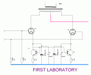
Dear Colleagues. Suggest improvement PP stages. Simple method to set current mirrors.
Have used exactly that arrangement myself.
Shoog
Individual cathode resistors (and bypass capacitors) for
the push and pull sides gives much reduced residual DC with imbalanced output valves. Assuming the two cathode resistors are closely matched, the local feedback (at DC) sets each output valve closer to its desired quiescent current.
(A shared cathode resistor sets the two bias voltages to be equal but allows the two
currents to be different.)
. Equalizes mirror currents. On the cathodes set different potentials. Short AC voltage capacitors.
Alternatively you can cap bypass cathode to cathode for differential behaviour - but this works better with a Wilson current mirror because the impedances are equally high.. Equalizes mirror currents. On the cathodes set different potentials. Short AC voltage capacitors.
Alternatively substitute simple CCS for even better performance.
Shoog
There will be no DC-offset if idle currents are simply adjusted equal.
Or do I miss some point from the original question ???
Or do I miss some point from the original question ???
There will be no DC-offset if idle currents are simply adjusted equal.
Or do I miss some point from the original question ???
If you like adjusting your bias points on a monthly basis thats fine. Some people seem to enjoy fiddling.
Shoog
Do you prefer to have a noticeable dc-offset as it is ?
I prefer to eliminate it by adjusting it to zero.
Even an ordinary cathode bias will keep the dc-balance if once adjusted.
I prefer to eliminate it by adjusting it to zero.
Even an ordinary cathode bias will keep the dc-balance if once adjusted.
Do you prefer to have a noticeable dc-offset as it is ?
I prefer to eliminate it by adjusting it to zero.
Even an ordinary cathode bias will keep the dc-balance if once adjusted.
Balance in the flow of time is broken.
Attachments
I love the concept of a PP amp in one bottle (plus driver of course). I use 6AS7 driven by 12L8GT for exactly that reason.
Shoog
Shoog
Trying to think of a suitable candidate for a SPUD PP using a mild step up input transformer.or "driven" by an input transformer if the output tube is easy to drive 🙂
Sorry for the OT 🙄
Shoog
- Status
- Not open for further replies.
- Home
- Amplifiers
- Tubes / Valves
- Question: Acceptable DC current in push-pull output transformer due to tube mismatch?