I tried to find the answers here in the forum and in common literature about Jfets but wasn't lucky.
When building buffers in a voltage follower topology with Jfets, i understand Jfets have to be matched for IDSS. Pinch off voltage etc seems not to be of importance in this application, but is important for voltage amplifiers.
So far so good. Here come my questions:
1- what is the actual audible effect on mismatched channels, for let's say one channel with a 10mA Jfet and the other channel with a 7mA Jfet?
As far as my current understanding goes, both channels will have a different output impedance, what can lead to creating a high pass filter when an amplifier with low input impedance is connected to the Jfet output. So for example if i connect a 1kOhm input impedance to my Jfet circuit. Is that right?
Based on this assumption, could i mismatch the Jfets i have when i know that the following stage has a high input impedance, like 1 MOhm?
2- I read Mr Pass goes for a max of 2mA stereo mismatch in his line stages. While other designers here even match their Jfets with 0.01mA accuracy. Is that high accuracy really needed? Do i only need that high accuracy in voltage amplifiers?
3- i read different opinions on bias. Some say to cascode with 80-90% IDSS for best sound, while official literature says to run a Jfet at 50% IDSS to allow maximum swing. This is quite contradictory, so i may have missed something. Or is it just another H2 related thing?
The drain current Id depends on both the Idss, Vp and Vgs according to Id = Idss( 1 - (Vgs/Vp)^2 ) so pinch off voltage Vp is also important.
And all this is temperature dependent. There is a bias point at which the temperature coefficient is zero - when Vgs = Vp + 0.063 V, so again you have to consider pinch off voltage
And all these parameters are totally different from one jfet type to another.
So a question about audible effects of Idss mismatch is not so straightforward!

Thank you.
So Vp is also important in a voltage follower "buffer", right? This is also what i understood from the literature and it makes sense in a logical way.
But why the heck is everyone only matching IDSS? At least that is what people are talking about when designing voltage followers.
So Vp is also important in a voltage follower "buffer", right? This is also what i understood from the literature and it makes sense in a logical way.
But why the heck is everyone only matching IDSS? At least that is what people are talking about when designing voltage followers.
There is a bunch of stuff on the web about source followers at, in some cases excruciating detail. But the importance of correctly biassing a fet voltage follower is here https://www.mathews-engineering.com/uploads/8/2/2/6/82266386/sourcefollowerbiaspoint.pdf
And the 34 minute excruciating detail is here
.
A relatively simple circuit is surprisingly complex.
Something easier to digest is Erno Borbely's article here https://audioxpress.com/article/JFETs-The-New-Frontier-Part-2.html
And the 34 minute excruciating detail is here
A relatively simple circuit is surprisingly complex.
Something easier to digest is Erno Borbely's article here https://audioxpress.com/article/JFETs-The-New-Frontier-Part-2.html
That came to my mind when i went to town today.no need to match both
A higher IDSS should mean the Jfet has a wider channel. So it will need more negative Vp to close it.
And that's why i think in a voltage follower where voltage on the output is always around 0.9x the times of the input, i wouldn't need to worry about stereo volume imbalance. But i wonder still what the actual effect of IDSS/Vp imbalance could be in a buffer. And if there is a measurable effect, will it be audible.
Thanks for sharing, but that is the literature i was referring to. It doesn't give me answers on my questions. Maybe it does but i can't see it (yet).Borbely's article
Thanks, i also read that and saved it as PDF some time ago.Rod Elliott devotes a page to the subject.
Does it offer the answer to my question? If yes, i missed it.
I suspect the "definitive" answers you seek to your questions would best come from people who are no longer members here with extensive semiconductor fabrication expertise (for example, scout wurcer, retired fellow from analog devices). in the meantime, you'll probably just have to experiment, share your findings and see what comes out of the conversations that result. good luck!
This paper supports Vp and Idss being related for a geometry. Variation in doping during manufacture gives the spread of these parameters
https://www.kennethkuhn.com/students/ee351/jfet_basics.pdf
https://www.kennethkuhn.com/students/ee351/jfet_basics.pdf
What i'm basically about is the question if it makes an audible difference when Jfet stereo pairs are mismatched in a voltage follower buffer.
For example both channels running at 90% IDSS, but the left channel at 10mA and the right channel at 7mA.
I guess not. And it would be great to have that confirmed because it opens doors when planning circuits. I wouldn't need to buy x-dozens of sometimes rare transistors for exact matching. Circuits with voltage amplification aside now.
Actually i'm surprised that i don't get answers or at least opinions straight out of the gun, since there are thousands of discussions about matching Jfets on this forum.
I suspect that is because no one has done the specific test of comparing two FET's both with closely matched Idss and two with poorly matched Idss.
Asking for an opinion is not going to get any answers either.
Perhaps this is the wrong forum to ask the question. Try https://pinkfishmedia.net/forum/ , there seems to be a lot of audio opinions on there.
Asking for an opinion is not going to get any answers either.
Perhaps this is the wrong forum to ask the question. Try https://pinkfishmedia.net/forum/ , there seems to be a lot of audio opinions on there.
I won't be happy with just an opinion. I'm asking for experiences or knowledge in the first place. But to have at least an opinion as a base for discussion would be nice.
Don't you find it weird too, that there is so much fuzz about Jfet variation, matching etc and in the end nobody comes up with a proper explanation why to match in a buffer? I thought once i asked, a Calvin or Nelson shows up and says "Hey that's because of H2. You want your amount of H2 to be the same in both channels" or something.
Or maybe someone would just say "It doesn't really matter. It's nearly hypothetical. Going for BL or GR channel wise is enough as long as you run them in saturation mode".
And the latter would be cool because i could use all my 2SK170BL leftovers, that vary between 7 and 12mA. Currently i'm building a four channel buffer. Three channels are well matched, but the fourth is off by 3mA and i don't have any better option but buying (possibly fake) NOS 2SK170BL that could probably be in a whole other ballpark IDSS wise.
You can buy matched LSK170 quads from the diyAudio store here https://diyaudiostore.com/collections/jfets/products/matched-jfets
OK, so i'm building the four channel buffer anyways with one channel off at about 3mA...
What differences between the matched and the unmatched channel am i supposed to measure and how do i do that?
I have a Tascam US144 MK2 USB soundcard, a DMM, 2 channel 20mHz oscilloscopes and a UMIK 1. Maybe not the best setup for measuring, but i assume what i can't measure, i will also not hear.
What differences between the matched and the unmatched channel am i supposed to measure and how do i do that?
I have a Tascam US144 MK2 USB soundcard, a DMM, 2 channel 20mHz oscilloscopes and a UMIK 1. Maybe not the best setup for measuring, but i assume what i can't measure, i will also not hear.
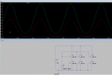
A quick LTSpice simulation of 3 buffers. Two pairs matched, but different Idss bins, the 3rd a mixed set
This shows that the matching of follower and source load matters more than anything else. The 3rd pair with mismatch has severe gain error and distortion
The 2N4117, 2N4118 and 2N4119 in LTSPice are the same family
This shows that the matching of follower and source load matters more than anything else. The 3rd pair with mismatch has severe gain error and distortion
The 2N4117, 2N4118 and 2N4119 in LTSPice are the same family
Attachments
Awesome, thank you. But that is actually not the case of mismatch i meant. What i mean is for example these stereo pairs (upper/lower transistor IDSS):
Left
10mA/8mA
10mA/8mA
Right
10mA/8mA
12mA/9mA
Or could be anything else. But i assume that the lower transistor is always around 80 to 90% the IDSS of the upper transistor.
So basically a stereo mismatch only.
Left
10mA/8mA
10mA/8mA
Right
10mA/8mA
12mA/9mA
Or could be anything else. But i assume that the lower transistor is always around 80 to 90% the IDSS of the upper transistor.
So basically a stereo mismatch only.
I think much cheaper and better matched is JFE2140You can buy matched LSK170 quads from the diyAudio store
- Home
- Source & Line
- Analog Line Level
- Question about the effects of matching jFETs