I have a question, if I may.
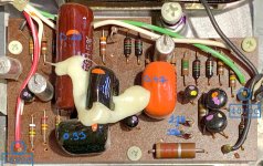
The attached is the tape equalization preamp of my Technics RS9900, a two-part cassette deck from the late 70s. I only have the electronics, not the tape drive.
I was hoping to use it as the preamp for a 1960s Revere cartridge player, which originally had a tube amp. Those cartridges run at 1-7/8ips also, like cassettes.
I prepared a (complicated) power supply for the Technics (as the PSU is in the mechanical part), all the jacks and cables and tried it. It seemed to work well, except the input from the Revere heads are too high, the Technics’s VU meters are hitting the upper end and there is / maybe some distortion. This is all with pre-recorded original tapes from the 60s.
I thought if I add an about 50kΩ resistor in series with the input signal, that would result in a bridge with the existing 22kΩ input bypass resistor and reduce the input signal. What happened instead is, the hum pick-up (which was minimal before) became the dominant signal, pushing the VU meters to their limits, without any music signal.
Is there a better way to tame the input from these — high output / impedance — tape heads? (They measure 650mH and 775Ω, per channel). Do I have to increase the feedback loop in the amp to reduce the amplification? Is there a simpler method without diving into the innards of the Technics, that I am missing?
My electronics knowledge is a bit limited… I would very much appreciate any opinions / suggestions.
Attachments
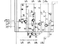
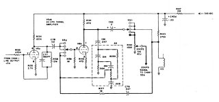
You could try increasing R211 (if that's what it is called, the 33 ohm resistor at the emitter). Do you know how much you need to reduce the gain?

Thank you, no — I will have to reduce the gain by trial and error.
The other thought I had was simply reduce the output of this stage, there is already a potentiometer to do that (VR 205. Not sure what that resistor tapped into the middle of it is?) and various other resistors to play with. I suspect overloading at these low levels may not be an issue?
Amicalement
The other thought I had was simply reduce the output of this stage, there is already a potentiometer to do that (VR 205. Not sure what that resistor tapped into the middle of it is?) and various other resistors to play with. I suspect overloading at these low levels may not be an issue?
Amicalement
If the problem is that the heads are much higher output than the preamp is designed for, overload may be occurring within the preamp itself, so padding the output won't help. I'm with Marcel, just increase that 33R resistor. Try 100R for ~10 dB less gain, 330R for ~20 dB. I'd be surprised if one of those wasn't enough. Easy to try, easy to revert if it doesn't work for you.
Edit: a better picture of the schematic would help, the service manual in Elektrotanya doesn't seem to have the schematics...
Edit: a better picture of the schematic would help, the service manual in Elektrotanya doesn't seem to have the schematics...
Last edited:
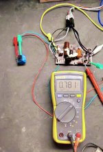
For this application it should be linear.I installed a 10K log potentiometer in series with the 33Ω emitter resistor
So I tried this and it works.
It seems all I need is 23-24Ω extra, so for a total of 56Ω. What decrease would that be, 5-6dB?
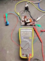
Much above that, to my ears at least, it started losing treble notes. But that is of course subjective, it could just be that as the volume declined I could hear less of the treble…why otherwise would an increase in emitter resistance interfere with the active filter / equalization loop?
As I increased the resistance further, at some point, it cuts out completely and starts producing a beeping sound.
Again, many thanks for the advice
It seems all I need is 23-24Ω extra, so for a total of 56Ω. What decrease would that be, 5-6dB?
Much above that, to my ears at least, it started losing treble notes. But that is of course subjective, it could just be that as the volume declined I could hear less of the treble…why otherwise would an increase in emitter resistance interfere with the active filter / equalization loop?
As I increased the resistance further, at some point, it cuts out completely and starts producing a beeping sound.
Again, many thanks for the advice
The above project was a success, thank you again. I have a new question.
The attached is the auto-reversing circuit from a mid-1960s Ampex 1000 / 2000 tape recorder. If the end of a tape has a short 20Hz signal, the circuit awakens, the solenoid energizes, motor, switches get reversed.
These were used in American and some Japanese machines. European machines used metallic tape to signal reverse. My tape players are all European but unfortunately almost all pre-recorded tapes are of US origin. In the past I added metallic tape to some of those but now I want to add this circuit to my Grundig TS1000 and Philips N5540.
I bought a “parts only” Ampex ($19) on eBay, extracted this circuit, made extension cables and have been experimenting. First, I am very impressed with how well it works. It is quite sensitive — only 17 to 22Hz gets through, and that with its 60 year old capacitors. It is also quite small, about 10 X 5cm. I will put it in a project case, provide the 35-40V it uses and add it — first — to the Grundig’s auto reverse circuitry (just need to short a switch momentarily).
I swapped the giant solenoid (L401) with a subminiature 12V relay, over a 690Ω resistor. It appears to work fine. However, I presume due to the much smaller current draw of the relay (31 vs 335mA), the voltage across R418 (with 20Hz applied as indicated) rises from 19V with the solenoid, to 23V with the relay. The voltage at the base of Q405 drops from the specified 2.3-2.5V to 1.5V. All transistors are silicon.
As I said, it works but I would like to make a small change to make it run closer to spec. My question is, what may that be? Should I try to increase R418? Play with the emitter resistor R419? Can I reduce the supply to 25VDC like it is in the earlier stages of the circuit?
I would very much appreciate any suggestions and all the best,
Ali Elam
Attachments

Last edited:
I think you get close when you just disconnect R420.
How do tape recorders like that work with organ music?
How do tape recorders like that work with organ music?
Thank you. I do not know. If I can locate one to play, I will find out and let you know! Almost all prerecorded tapes in the US
were also manufactured by Ampex, regardless of label. I suspect there was nothing on them below 22Hz. But you are right. I should add a power switch to this circuit for times it becomes annoying.
Disconnect or bypass — keep the diode? What do you think R420 and its diode in series do?
were also manufactured by Ampex, regardless of label. I suspect there was nothing on them below 22Hz. But you are right. I should add a power switch to this circuit for times it becomes annoying.
Disconnect or bypass — keep the diode? What do you think R420 and its diode in series do?
Don't bypass, just disconnect or remove R420. You can leave the diode in or remove it, it doesn't do anything anyway when R420 is disconnected.
Their purpose is to keep the voltage at the emitters of Q404 and Q405 from increasing excessively when the circuit drives a 335 mA load, but I don't know why they didn't just use a smaller value for R419. Maybe to ensure the circuit also works with lighter loads, if the same PCB is used in different tape recorder models?
Their purpose is to keep the voltage at the emitters of Q404 and Q405 from increasing excessively when the circuit drives a 335 mA load, but I don't know why they didn't just use a smaller value for R419. Maybe to ensure the circuit also works with lighter loads, if the same PCB is used in different tape recorder models?
Yes, Ampex seems to have used this circuit in dozens of different models. In fact the only other reversing circuit they have built appears to be a tube / valve version. Interestingly, it is from the same period, mid-60s. I remember there was an Ampex website of retired engineers where you could ask questions but I am not sure if it still exists.
I am curious, does the diode conduct at some point, 0.7V or so and keep the voltage level?
I am curious, does the diode conduct at some point, 0.7V or so and keep the voltage level?
Attachments
Yes, more or less. The voltage at the base of Q405 is supposed to go to 2.4 V, so its emitter voltage will then be about 1.7 V. Considering the current level, that must be about 1 V across the diode and the rest across the 1.8 ohm.
I have another question, if I may.
I wanted to convert an extra, Cambridge-brand RIAA (record player) preamplifier that I have, to use it with a 19cm/s NAB tape player. The pole points in each compare as follows:
RIAA — 50, 500 and 2122Hz (3180, 318 and 75μs)
NAB — 50 and 3150Hz, only (3180 and 50μs)
The attached are the full preamp, the RIAA filter section that I simplified (they seem to have used multiple capacitors and resistors in parallel or in series) and what I did.
As a first thing, I removed C81 to get rid of the 2122Hz pole. Then I bypassed R22 with a jumper, and reduced the 2400 Ω resistor (green box, R8+R9, in the main schematic) to 1265Ω, with the intention to increase the 500Hz pole to 3150Hz.
The preamp works fine but, to my ears, it sounds thin, meaning treble is stronger than it should be. I figure I messed something up in my calculations but not sure what? I would very much appreciate any suggestions.
Also the preamp could use a bit more gain and again I am not sure where the best place is to achieve that. I am using the MM (moving magnet) input.
Many thanks in advance for any help you can give me.
Attachments
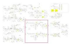

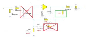
It's R45 that you need to make 1.265k. Bypass the 2.4k resistor, the rest as it is (R19 = 76k, C81 removed, R22 bypassed). You can also bypass R24, it serves no purpose with C81 removed. And, although C75 and C21 are now in parallel, depending on the PCB layout, it may be a good idea to leave C75 in place, especially if it's close to the opamp and C21 not so close.
Edit: this will also increase the gain but probably not enough. If that's the case, the easiest way to increase it is to reduce R62 / R79 (in the MM input section to the left, the feedback resistor to ground next to the opamp) from 91R to, say, 47R for ~6 dB more gain, adjust to taste from there.
Edit: this will also increase the gain but probably not enough. If that's the case, the easiest way to increase it is to reduce R62 / R79 (in the MM input section to the left, the feedback resistor to ground next to the opamp) from 91R to, say, 47R for ~6 dB more gain, adjust to taste from there.
Last edited:
- Home
- Source & Line
- Analogue Source
- Question about tape equalization preamp