Hi all,
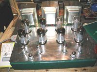
I made a PP EL34 amp and I have a question on its B+ behaviour.
The simple power supply is
350V -> bridge (1N4007) -> 470uF -> 5H -> 470uF
It takes 17.5 seconds for the amp to spit out any sound. Is my heater supply "slow" and the EL34 conducts longer? The B+ goes to a high of 460V first before settling down to 416V (420V target) after 20 seconds.
Is there a danger to this behaviour?
Cheers!
Hi,
That will depend on the insulation of the cap behind the bridge.
At worst you'll see 350*1.4 = 490VDC provided the mains is stable.
If you want to reduce it use some resistance in both legs of the primary or use a NTC.
Cheers, 😉
Is there a danger to this behaviour?
That will depend on the insulation of the cap behind the bridge.
At worst you'll see 350*1.4 = 490VDC provided the mains is stable.
If you want to reduce it use some resistance in both legs of the primary or use a NTC.
Cheers, 😉
Hi,
Dang....I meant to write secondary, the winding you use for your B+, not the mains primary, that would bring all voltages down.
I don't know what tube(s) are causing this but don't expect a tube amp to play full blast after 20 secs of warm up.
If you should do this expect damage to the output tubes' cathodes (stripping away emissive materials).
17+ seconds for any audible sound to come through seems rather long, OTOH some people go to great lengths to achieve just such a slow start....😀
IOW, without seeing the actual circuit it's hard to tell what causes the slow ramp up.
Cheers, 😉
If you want to reduce it use some resistance in both legs of the primary or use a NTC.
Dang....I meant to write secondary, the winding you use for your B+, not the mains primary, that would bring all voltages down.
so does that mean the 17.5 second "delay" is ok?
I don't know what tube(s) are causing this but don't expect a tube amp to play full blast after 20 secs of warm up.
If you should do this expect damage to the output tubes' cathodes (stripping away emissive materials).
17+ seconds for any audible sound to come through seems rather long, OTOH some people go to great lengths to achieve just such a slow start....😀
IOW, without seeing the actual circuit it's hard to tell what causes the slow ramp up.
Cheers, 😉
fdegrove said:Hi,
Dang....I meant to write secondary, the winding you use for your B+, not the mains primary, that would bring all voltages down.
I thought I read secondary

I have a pair of 12R 50W resistors here which I can try. But with 500V on the caps, is that something I will be worried about?
frank, it is this one - http://www.diyaudio.com/forums/showthread.php?s=&threadid=29351IOW, without seeing the actual circuit it's hard to tell what causes the slow ramp up.
Cheers, 😉
Hi,
550 V would be safer if you can lay your hands on one....as a figure of speech I mean.
I had a look at your circuit, it doesn't show the power supply so I'm still in the dark.
If you used big caps in the PS it's going to take some time for them to charge but other than that I wouldn't worry about the warm up delay if I were you.
Leaving a tube amp to warm up for half an hour is common practice after all.
Cheers,😉
EDIT: just saw it when submitting the post:
That's big enough to explain the delay.
I have a pair of 12R 50W resistors here which I can try. But with 500V on the caps, is that something I will be worried about?
550 V would be safer if you can lay your hands on one....as a figure of speech I mean.
I had a look at your circuit, it doesn't show the power supply so I'm still in the dark.
If you used big caps in the PS it's going to take some time for them to charge but other than that I wouldn't worry about the warm up delay if I were you.
Leaving a tube amp to warm up for half an hour is common practice after all.
Cheers,😉
EDIT: just saw it when submitting the post:
350V -> bridge (1N4007) -> 470uF -> 5H -> 470uF
That's big enough to explain the delay.
thanks frank!
yeah, not even when the power is off 😀 😀 😀
550 V would be safer if you can lay your hands on one....as a figure of speech I mean.
yeah, not even when the power is off 😀 😀 😀
EL34s have huge cathodes that take a long time (about 20 secs!) to warm up and start conducting. But they have great transient response as a result. More electrons = more peak current!
I would install a B+ (standby) switch after the diodes but before the first filter cap. This allows you to warm up all the tubes before you slam the high voltage on them. You could rig a timer circuit with a 555 chip and a relay if you only want one switch.
Also I find 1n4007 a little weedy for my liking. You should be using 1N5408 at the very least!
hi shifty,
all my set amps have standby switches. i thought about that for this amp but left it out in the process. so in it will go 🙂
i'll replace the diodes with your recommendation.
thanks!
all my set amps have standby switches. i thought about that for this amp but left it out in the process. so in it will go 🙂
i'll replace the diodes with your recommendation.
thanks!
Hi there......in my service racks I always replace discrete PSU HV diodes with encapsul bridge types.......Diodes on same Silicon die make less noise.....
Soft start posibilities is large......on all my t'amp inrush circuits ..I allow nearly half- minute for KT88/6550' amp to warm-up....I use 22R 25W WW res in series with prim winding 650VA tranny. This W.W res is S/C by relay after 15 secs. ......after this (soft-start relay) has closed, allow another 10 secs for interstage B+ to reach spec volts .....total before sound gets through = 25secs approx. Nothing unusual.....
General rule; electrolytic caps are usually run at between 0.8-0.9 of stated working voltage. Don't go higher unless surge value is stated.
I'm not sure about the effects on tube life with B+ already ramped up at peak 1.414 AC= DC volts before tube anodes + g2 are conducting..... my trade notes mentions this was bad practice on output tubes. Can anyone illustrate why this is detrimental to tube life.......?
rich
Hi,
Actually it isn't bad practice provided you don't try to draw current before the cathodes have fully warmed up.
I wouldn't implement it in a commercial offering but leaving the caps charged keeps them formed. Well electrolytic ones anyway.
Primary as in on the mains side of the xformer?
Cheers,😉
my trade notes mentions this was bad practice on output tubes. Can anyone illustrate why this is detrimental to tube life.......?
Actually it isn't bad practice provided you don't try to draw current before the cathodes have fully warmed up.
I wouldn't implement it in a commercial offering but leaving the caps charged keeps them formed. Well electrolytic ones anyway.
I use 22R 25W WW res in series with prim winding 650VA tranny.
Primary as in on the mains side of the xformer?
Cheers,😉
fdegrove said:
Primary as in on the mains side of the xformer?
Yes...my power demands are somewhat different...That triple B+ switchable amp alot want to see....(photo here); B+'s can be selected for tube longevity (and different types) to select Pout's of 25W+25W; 130W+130W using parall-paired 6550's; or full wacker 200W+200W (>800W bridged) at 600V B+ with 8x JJ KT88's. That's the reserve headroom for my trumpet.... Note with boost mode switchmode technology the comparative size of mains tranny compared with each o/p transformer. Total chassis weight ca, 65kg.
For power transformers above 150VA, I'm against fitting soft start resistors in H.V secondaries due to risk of serious arcing assisted by winding parasitics resonating by failing fuse..
With constricted chassis space I wound the E&I beast (in centre) with a higher B max (1 to 1.35Twith a higher temp rise than orig) ....Drawback is that primary inrush current is higher and without prim start ballast resistor would annoyingly knock out AC mains currrent limit breaker and blow primary fuse. It behaves somewhat like a <soggy toroid>... . Trick is to select resistor rating, so combination of transformer primary winding resistance and of B+ cap(s) can charge up over several AC cycles. I can use a F3.15A fuse without popping on a 650VA transformer.
An advantage with start up ballast in primary is a lower fuse rating can be used, so long the soft-start relay can "knock out" fast enough on a sudden supply interruption, i.e before the supply kicks back on the peak of the following cycle.
For those interested in designing powerful tube amps with large 2:1 current swings, protection watchdogs are essential to save the tubes and output transformers in failure conditions. Unnecessary complication....No.....not with todays electronics. Sequencing logic between neg bias and B+ is easily done......with inhibiting lockouts and hot switching.
For some years I've been using discharge resistors in series with 30V zener diodes across each set of hi C value electrolytics esp in stepped cap arrangements to boost voltage ratings, ......as you rightly mentioned to keep the electroyte film healthy & encourages cap memory effect....it also greatly reduces on-surge start-up currents.......Others take note...
Viva..........800W at 0.25% THD...... the ultimate in gobsmacked trumpet power.......or deepest pedal bass.....
rich
Attachments
Hi,
Good idea, I'll try to remember that.
Mighty big amps you have there...
Cheers,😉
it also greatly reduces on-surge start-up currents.......Others take note...
Good idea, I'll try to remember that.
Mighty big amps you have there...
Cheers,😉
Yes Frank.......with brilliant spec...that will be the last of mammouth designs.....only a handful of well made tubes will take that slaughtering B+ voltage...... I will concentrate on preamps...and more humble things..enclosed small glimpse THD graph (if this comes through). I will ztry and get some soft start arrangemnts on this for others to get ideas.
rich
rich
Attachments
10nF snubber cap
Hi arnoldc
Maybe adding a 0.01uF 2kV ceramic cap across the 350V secondary before the sand bridge to reduce rectifier swithching noise. I know it worked miracles in my SS rectified tube preamp. Couldn't hurt. And no I aslo don't think 17 sec is too long. I would also change the first cap (470uF) to a lower value, say 220uF. Less chance of power supply ringing and your power transformer would run cooler. I'm guessing you take your power for the output section after the 5H choke, correct?
Cheers
Wayne
For some years I've been using discharge resistors in series with 30V zener diodes across each set of hi C value electrolytics esp in stepped cap arrangements to boost voltage ratings, ......as you rightly mentioned to keep the electroyte film healthy & encourages cap memory effect....it also greatly reduces on-surge start-up currents.......Others take note...
Good idea, get the ole soldering iron heated up!
Also having a fairly large cap say around 68nF - 100nF across the mains switch also allows a small current to flow although not nearly enough, 5V or so in my amp's PS IIRC.
Wayne 🙂
Re: 10nF snubber cap
hi wayne, i've seen on some schematic that each diode is shunted with these ceramic caps. will it have the same effect as you described? or i can do both?
thanks wayne!
cogsncogs said:Hi arnoldc
Maybe adding a 0.01uF 2kV ceramic cap across the 350V secondary before the sand bridge to reduce rectifier swithching noise.
hi wayne, i've seen on some schematic that each diode is shunted with these ceramic caps. will it have the same effect as you described? or i can do both?
i used PSUD to model the power supply and i will surely try the 220uF. yes, i do take the power for the EL34s after the choke. i was planning to have another choke for the driver section sometime soon.I know it worked miracles in my SS rectified tube preamp. Couldn't hurt. And no I aslo don't think 17 sec is too long. I would also change the first cap (470uF) to a lower value, say 220uF. Less chance of power supply ringing and your power transformer would run cooler. I'm guessing you take your power for the output section after the 5H choke, correct?
thanks wayne!
Re: Re: snubber caps
Hi arnoldc
You can do either or both or all the way around! Here's where a good dual trace 20mHz or better scope comes in handy. If you don't have one or can't borrow one use your ears. Try different combinations, it's different for each Pwr xformer, grounding scheme etc. I've attached a generic schematic. All caps are 2kV.
Wayne 🙂
Hi arnoldc
hi wayne, i've seen on some schematic that each diode is shunted with these ceramic caps. will it have the same effect as you described? or i can do both?
You can do either or both or all the way around! Here's where a good dual trace 20mHz or better scope comes in handy. If you don't have one or can't borrow one use your ears. Try different combinations, it's different for each Pwr xformer, grounding scheme etc. I've attached a generic schematic. All caps are 2kV.
Wayne 🙂
Attachments
Re: Driver section
You could try a 1N4007 in series with a dropping resistor in place of the choke. What I've heard called a poor man's regulator. That's what I have in my amp. Say the output section draws enough current say on a signal peak or a sustained 19Hz organ pedal note!, and the voltage where the output section taps from drops below the voltage where the driver section taps from. The diode prevents the driver section bypass cap from discharging back into the output section bypass cap. At least that's the theory behined it.
I hope I explained that clearly.
Also I'd like to add that if you're using your ears to check for rectifier switching noise, it sounds like buzzing at your pwr line freq. Altough the actual frequency is in the hundreds of kilo hertz to mega hertz range. You may not be able to actually here it at all, that's where a scope comes in handy. I do know from my experience, once you get rid of it your amp/preamp sounds much cleaner. Opens everything up!
Try it!
Wayne 😀
i was planning to have another choke for the driver section sometime soon.
You could try a 1N4007 in series with a dropping resistor in place of the choke. What I've heard called a poor man's regulator. That's what I have in my amp. Say the output section draws enough current say on a signal peak or a sustained 19Hz organ pedal note!, and the voltage where the output section taps from drops below the voltage where the driver section taps from. The diode prevents the driver section bypass cap from discharging back into the output section bypass cap. At least that's the theory behined it.
I hope I explained that clearly.
Also I'd like to add that if you're using your ears to check for rectifier switching noise, it sounds like buzzing at your pwr line freq. Altough the actual frequency is in the hundreds of kilo hertz to mega hertz range. You may not be able to actually here it at all, that's where a scope comes in handy. I do know from my experience, once you get rid of it your amp/preamp sounds much cleaner. Opens everything up!
Try it!
Wayne 😀
hi wayne,
you made a mention about the low bass...
the amp i prototyped got a very good midrange in which i was surprised myself. however, it definitely is lacking in the bass department, more so low bass. it is like it's there but it isn't. like running out of steam if i may say.
i am trying to pinpoint the cause and am looking at the output transformer which is custom wound 5K p-p 80mA per side, or the power supply.
the PSU if i may add uses Lundahl LL1648, which i believe is rated at 600mA but only 60% of that is available at how i use it.
a) i thought the OPT might be saturating, so i asked for a 6k6 p-p 100mA per side to me made for me
b) change the Lundahl power transformer
i'd appreciate if you could share your experience on this having built that magnificent PP amp of yours.
- Status
- Not open for further replies.
- Home
- Amplifiers
- Tubes / Valves
- Question about PP EL34 power supply behaviour