Hi,
I have built a DAC with DIR1703 and AD1864 to play 44.1kHz 16bit CDs
My plan was to use the Current output mode for AD1864 into a I-V tube converter.
The problem: At Iout from AD1864, both channels looks very saturated.
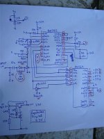
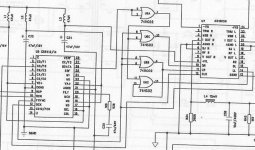
Below, the scheme.
- load for Iout = 100 ohms
- all inverters 74HC04 at 3.3V
- R feedback for first SPDIF inverter = 22K ohms
Could someone point where is the error?
Could some of my ICs be damaged?
I have built a DAC with DIR1703 and AD1864 to play 44.1kHz 16bit CDs
My plan was to use the Current output mode for AD1864 into a I-V tube converter.
The problem: At Iout from AD1864, both channels looks very saturated.
Below, the scheme.
- load for Iout = 100 ohms
- all inverters 74HC04 at 3.3V
- R feedback for first SPDIF inverter = 22K ohms
Could someone point where is the error?
Could some of my ICs be damaged?
Attachments
You are sending 16-bit right justified data to a device expecting 18-bit right justified data. Delay LRCK by 2 BCK cycles.
Thanks a lot!!!!!
Yes. Shure it is the problem!
Is the delay circuit that one used in Audionote DAC 1.1 ? If not, do you suggest some scheme for delay circuit?
What pins in DIR1703 are equivalent to CS8412 FSYNC, SDATA and SCLK ?
I have IC 74AC02 on hand. Can I use it at 3.3V to make the delay circuit or do I have to use the 74HC02 ? Should I use 3.3V or 5.0V ?
Thanks again
Attachments
The Audionote circuit does not apply here. In that circuit the data from the CS8412 is 18-bit right justified data. The DIR1703 does not have that option, so 'AC02's alone will not be much use. You will need flip-flops.
hum...
looking at DIR1703 and AD1864 datasheets, I'm in doubt if "delay LRCK by 2 BCK cycles" will work.
From AD1864 datasheet:
- The last 18 bits sent to DAC will be converted to output when LL or LR goes to "0".
From DIR1703 datasheet:
- From graphs at pag. 13 and 15, it looks each LRCKO cycle (L+R data) has a fixed 64 BCKO. So, in theory, each channel has a "space" for 32 bit data.
So, AD1864 receive last 18 bit when LL/LR goes to "0".
If I have configured DIR1703 for 16-bit MSB first, right justified, AD1864 is receiving an undefined value for 1st and 2nd MSB for his 18-bit internal register.
I dont know if playing only 16bit Cds, I can put DIR1703 to output 24-bit MSB first, right justified.
Nor, if it works, I dont know if DIR1703 would convert 16bit data to 24bit correctly
ex: 1111111111111111 (16-bit) to
00000000111111111111111111 (24-bit)
or if the 8 MSB from 24bit word would still be undefined
ex: xxxxxxxx1111111111111111
Help!
SandroN said:hum...
looking at DIR1703 and AD1864 datasheets, I'm in doubt if "delay LRCK by 2 BCK cycles" will work.
Thats my cue to leave the stage.
change DIR1703 output to 24bit didn't fix the problem. Sound changed to a high freq noise like white noise.
Change back to 16 bit
Change back to 16 bit
The AD1864 datasheet is confusing. 
The timing diagram at the bottom of page 7 shows left-justified data. Try setting the DIR1703 to 24-bit left justified.
edit: on second thought, it looks like the AD1864 is expecting 18 bits only and will not work with 16 or 24.
The timing diagram at the bottom of page 7 shows left-justified data. Try setting the DIR1703 to 24-bit left justified.
edit: on second thought, it looks like the AD1864 is expecting 18 bits only and will not work with 16 or 24.
Because of this, I think it will work if you delay LRCLK by 2 BCK cycle provided that dir1703 is in 16 bit right justified mode. The two smallest bits would be unknown, may be zero as they would be taken from the next data frame.
SandroN said:So, AD1864 receive last 18 bit when LL/LR goes to "0".
If I have configured DIR1703 for 16-bit MSB first, right justified, AD1864 is receiving an undefined value for 1st and 2nd MSB for his 18-bit internal register.
Since the AD1864 expects exactly 18 bits, it is neither right or left justified. It is 18-bit only justified. 😀
The DIR1703 can be used in either right or left-justified 24-bit mode but the bit clock will need to be disabled after 18 bits have been clocked in.
A counter and some gates or a small programmable logic chip will be needed.
The DIR1703 can be used in either right or left-justified 24-bit mode but the bit clock will need to be disabled after 18 bits have been clocked in.
A counter and some gates or a small programmable logic chip will be needed.
interesting thing about bitclock.
so, I could put DIR1703 at 24bit MSB Right Justified and Make some logics to only enable BCKO after 14 BCKO passed (32bits total space - 18bits data).
Is it?
so, I could put DIR1703 at 24bit MSB Right Justified and Make some logics to only enable BCKO after 14 BCKO passed (32bits total space - 18bits data).
Is it?
You can do that,
or,
the logic may be easier to set DIR1703 to left justified, allow 18 bit clocks after a LR clock transition, then disable all the rest of the bit clocks until the next transition of the LR clock.
😎
or,
the logic may be easier to set DIR1703 to left justified, allow 18 bit clocks after a LR clock transition, then disable all the rest of the bit clocks until the next transition of the LR clock.
😎
rossl said:Since the AD1864 expects exactly 18 bits, it is neither right or left justified. It is 18-bit only justified. 😀
I don't think so. Have you looked at figure 10 in the ad1864 datasheet? The timing of the rising edge of LL and LR is not important at all.
"falling edges of LL and LR cause the last 18 bits clocked into the Serial Registers to be shifted into the DACs"
This works based on a 18 bit FIFO register, I believe.
You may also note that the data format of AD1864 is exactly the same as that of AD1865. If what you said was true then AD1865 would never work with CS8412 in mode 6 (64 BCK per FSYNC and data is right justified with FSYNC edge). In fact, many commercial and DIY DACs were based on this design and they work perfectly.
Of course stop BCK is another solution to make it work.
quantran said:
I don't think so. Have you looked at figure 10 in the ad1864 datasheet? The timing of the rising edge of LL and LR is not important at all.
?? I didn't say it was. That is why is said left or right justified 24 bit would be usable.
quantran said:
This works based on a 18 bit FIFO register, I believe.
OK. So how do you want to make it work?
Clocking in two random bits from another data frame is not a good solution, in my opinion. That is not music.
I only wanted to point out that AD1864 needs 18 bit right justified format.
I believe that the first 2 bits of the next frame have fixed value. Though there is no documentation about this my best guess is that they are zero.
As such delay LRCLK by 2 BCK should work fine. Also if the DAC can get 16 larger bits right it would be quite good already.
Cheers
I believe that the first 2 bits of the next frame have fixed value. Though there is no documentation about this my best guess is that they are zero.
As such delay LRCLK by 2 BCK should work fine. Also if the DAC can get 16 larger bits right it would be quite good already.
Cheers
rossl said:
?? I didn't say it was. That is why is said left or right justified 24 bit would be usable.
OK. So how do you want to make it work?
Clocking in two random bits from another data frame is not a good solution, in my opinion. That is not music.
quantran said:
I only wanted to point out that AD1864 needs 18 bit right justified format.
A good solution does not need the DIR1703 to be configured in right justified.
"Right" or "Left" justified is only meanignful if there are extra bits.
quantran said:I believe that the first 2 bits of the next frame have fixed value. Though there is no documentation about this my best guess is that they are zero.
As such delay LRCLK by 2 BCK should work fine. Also if the DAC can get 16 larger bits right it would be quite good already.
Cheers
[/B]
It would be OK only if 16 bit CD data is connected to the DIR1703.
If the user ever wants to connect DVD with a 20 or 24 bit data stream to the DAC, your solution will not give 18 bit resolution. It will give 16 bit with noise.
I agree that it will not utilise the benefit of 20 or 24 bit sources.
But what do you mean by "16 bit with noise"? If 2 smallest bits are zeros do I have any extra noise?
But what do you mean by "16 bit with noise"? If 2 smallest bits are zeros do I have any extra noise?
can you guarantee that the two bits will always be zero? They are clocked from an unrelated data frame.
😀
😀
- Status
- Not open for further replies.
- Home
- Source & Line
- Digital Source
- Question about DIR1703