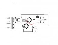
Hi all, I've currently at hand a transformer with three secondaries (all deriving from a single winding) for feeding two independand circuits: one for tube and the other one for S.S. I cannot treat it as it were center-tapped because voltage aren't balanced at zero (0-14-20Vac).
Furthermore, since I want to use a full wave rectifier (and not half-wave) I may have some trouble with resulting hum connecting respective grounds.
I found that with the below schematic, with elevated ground to heater's tube, no more noise comes out. Can anyone explain that or whether is there some error in my circuit? Thanks.
Attachments
Last edited:
Well it could be the two 220 ohm resistors are acting like a "humdinger " removing AC noise via the capacitor on the other rail .
And/or the heater elevation is reducing the leakage between the cathode and heater.
And/or the heater elevation is reducing the leakage between the cathode and heater.
Yes, this probably acts like a "humdinger" as you say. In fact I noticed that connecting the two supply gound together a little hum comes out.
I have to say that the higher supply (the second, with 29Vdc) has a further voltage doubler in series. This one could influence the ground path, causing some instability due to the presence of floating ground.
I have to say that the higher supply (the second, with 29Vdc) has a further voltage doubler in series. This one could influence the ground path, causing some instability due to the presence of floating ground.
If you have problems with multiple earths you could always try a 10 ohm resistor between them but that's in normal circumstances , what the outcome would be in your set up I have not tried .
Its down to reference points .
Its down to reference points .
I could rewind the secondary of the toroidal splitting it in two so I had separate AC lines, but it took too much work. Then I managed in this way.
At the momet the results are good for me, since also the low currents at stake (and less stress for diodes).
In a previous thread I followed the suggestion for a right grounding for the voltage doubler regulator and it seems to work. I'll try on a little nonstop working of the overall circuit and if everything is ok I think to keep like this.
Sorry, there was an error in the schematic they are 29Vdc.
I found that adding a small ceramic capacitor across the (floating) ground of the heater's supply and the positive on 29Vdc the hum nearly disappeared.
I found that adding a small ceramic capacitor across the (floating) ground of the heater's supply and the positive on 29Vdc the hum nearly disappeared.
Nowadays the "go to " HF oscillation reducer is a cog ceramic (NP) .
In the Old School Days for somebody like me it was Silver Mica capacitors , very widely used in radio communications of any sort be it American or UK .
I was absolutely shocked at the price of them in modern day 2021 , thank goodness I have a big supply , I thinks its down to supply of the raw stuff.
One thing I immediately learned while working on HF & VHF/UHF was the higher the frequency the lower the value of already small value capacitors used for stability till it reached the stage in UHF CRT tuners that even moving a connection a few mm mistuned the circuit .
The Motto ?--the higher the frequency the lower the value of capacitance used to remove/correct any high frequency problem and we are talking in the PF range NOT NF.
Yes the silver/mica capacitors todady are as expensive as gold on looking around. I don't know 20-30 years ago beacause it's some years that I'm interesting to electronics. Anyway I agree a value under the nF range in order to attenuate HF frequencies, I use to go with multilayer ceramic being pretty cheap.
I suspect now there's a sort of magnetic coupling with the small tube because when approaching a finger hum increases, maybe a metal cage (cylinder) around it could help.
I suspect now there's a sort of magnetic coupling with the small tube because when approaching a finger hum increases, maybe a metal cage (cylinder) around it could help.
The radiation that is transmitted by the SMPS is being stored in your body --your body is acting like a radio aerial that is given out by your body and being transmitted to the sensitive tube.
If you are keeping the power supply then you have to screen any lengths of connection wire in your amplifier that would act as an aerial ,remember to earth the screening .
If you are keeping the power supply then you have to screen any lengths of connection wire in your amplifier that would act as an aerial ,remember to earth the screening .
Yes I agree, then some tubes can be more sensitive than others because as for my experience they behave not all in the same way (tendence to microphonicity, inner materials etc.). Of course a driver tube will be influenced greater than a power tube.
The fact of shielded cables, in particular those bringing the signal path, is a good idea that I already used successfully in the past. Instead I never did this with the PSU cables, but with sensitive circuits maybe is a solution to be tried as you suggest.
The fact of shielded cables, in particular those bringing the signal path, is a good idea that I already used successfully in the past. Instead I never did this with the PSU cables, but with sensitive circuits maybe is a solution to be tried as you suggest.
- Home
- Amplifiers
- Power Supplies
- Question about dependent windings and hum