Hello,
I have been passionately reading up on all I could find on this topic, and I have gathered the following "bits of truth":
(1)
ALL low-pass filters cause a delay (Group Delay) in the output of the filtered speaker unit (e.g. Woofer) in its pass-band, resulting in an apparent backward shift of its acoustic centre
(2)
High-pass filters also cause a similar Group Delay, but in the speaker's stop-band; as a result, the apparent acoustic centre of the unit (e.g. Tweeter) remains approximately coincident with its physical position in the pass-band
(3)
ALL conventional symmetric crossover filters (e.g. 2nd order Linkwitz-Riley, 3rd order Butterworth, 4th oder Linkwitz-Riley, etc.) are designed to sum flat when the physical acoustic centres of the two speaker units (Woofer AND Tweeter) are aligned; however, given (1) and (2) above, this means that the two speaker untis are left to emit their respective portions of the audio band from substantially different apparent positions, which results in an overall NON-time aligned output from the speaker system (incidentally, Linkwitz-Riley crossovers do ensure phase matching of Woofer and Tweeter at all frequencies, which results in regular polar dispersion, but they still do not result in time-aligned output, since the latter depends on Group Delay, and not phase - see (1) and (2).)
(4)
It has been demonstrated that it is impossible to obtain: (A) perfect acoustic summing (flat frequency response), (B) perfect phase match AND (C) flat Group Delay using a simple analogue passive crossover [Vanderkooy, J. and Lipshitz, S. P., “Is Phase Linearization of Loudspeaker Crossover Networks Possible by Time Offset and Equalization?”, J. Audio Eng. Soc., vol. 32 (Dec. 1984)].
(5)
Given (3) and (4) above, a number of efforts have been made to design "quasi-optimal" crossovers that strike the best possible balance between the three goals (A),(B) and (C) (rather than only considering (A) - e.g. conventional 3rd order Butterworth, or (A)+(B) - e.g. even-order Linkwitz-Riley).
Two notable examples of "quasi-optimal" crossovers (5) are the ones developed by SPICA and by Jean Michel LeCleac'h (filtrage).
Both of these "quasi-optimal" crossovers use a physical offset between the physical acoustic centres of the Woofer and Tweeter to try and align their respective emissions over broad portions of the audio band.
The SPICA crossover uses a 4th order Bessel low-pass at Fx (+ polarity) and a quasi-first order high-pass at Fx (+ polarity), with an Offset = 0.435*c/Fx.
Unfortunately, the 1st order HP is often too bland to be usable with real Tweeters, especially of the horn-loaded Compression Driver type that I pefer.
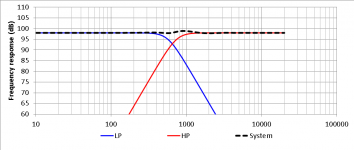
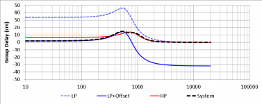
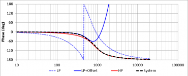
The JMLC crossover uses instead a 3rd order Butterworth low-pass at 0.87*Fc (+ polarity) and also a 3rd order Butterworth high-pass at 1.15*Fc (- polarity), with an Offset = 0.22*c/Fx.
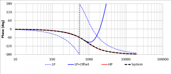
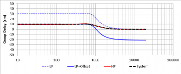
Below are simulations of the frequency response, phase and group delay of this type of crossover for Fx = 650Hz (attachments 1,2,3)
Overall, this is a much more practical solution than the SPICA one, and has been reported to work quite well by a number of users. However, the physical offset between the physical acoustic centres of the Woofer and Tweeter is rather small, and I have found that in the case of a system composed of a large-diametre Woofer and a compression driver + horn, for typical Fx values the horn ends up sticking quite a bit out in front of the Woofer cabinet.
Also, the phase match between Woofer and Tweeter (goal B above) isn't all that good, really, which results in a relatively poor polar response (this is often considered relatively unimportant by the proponents of the JMLC method, who typically listen on axis in the near field).
Finally, the group delay of the Woofer does not match that of the Tweeter at Fx, leaving the two units to emit from non-coincident positions at this important frequency where their output intensities are equal.
So I kept searching for alternative "quasi-optimal" crossover solutions.
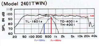
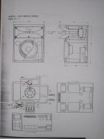
One (passive) crossover that always intrigued me and that has developed a bit of a "mythical" aura in some audio circles is that which was used by TAD in their professional monitor models 2401 and 2402 (attachment 4).
By reverse-engineering the published frequency response plots for the 2401 model (attachment 5), and measuring the approximate physical offset between the Woofer's dust cap and the compression driver's diaphragm, I was able to work out the following design criteria for this crossover type:
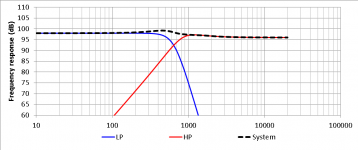
Woofer: 6th order Linkwitz-Riley low-pass at Fx (+ polarity) (attachment 6)
Tweeter: 2nd order Chebyshev (Q=1) high-pass at 1.3*Fx (- polarity), attenuated -2dB (attachment 7)
Offset = 0.6 * c / Fx
The resulting simulations of the frequency response, phase and group delay of this type of crossover for Fx = 650Hz are illustrated below (attachments 8,9,10).
Well, I must say I quite like it! 🙂
This "TAD-style" crossover clearly belongs to the "quasi-optimal" family, and exhibits a nice set of desirable characteristics, namely:
- smooth frequency response
- excellent phase match up until Fx (expected good polar behaviour)
- almost perfect group delay match at Fx, and smooth overall group delay curve, with both Woofer and Tweeter emitting from almost coincident positions over most of their respective pass-bands (i.e. very good "time alignmnet")
- conveniently large offset, which greatly facilitates the physical positioning of the Tweeter horn with respect to the Woofer box
I am posting all this in the hope that others may find it useful, too.
Comments are welcome!
Cheers,
Marco
I have been passionately reading up on all I could find on this topic, and I have gathered the following "bits of truth":
(1)
ALL low-pass filters cause a delay (Group Delay) in the output of the filtered speaker unit (e.g. Woofer) in its pass-band, resulting in an apparent backward shift of its acoustic centre
(2)
High-pass filters also cause a similar Group Delay, but in the speaker's stop-band; as a result, the apparent acoustic centre of the unit (e.g. Tweeter) remains approximately coincident with its physical position in the pass-band
(3)
ALL conventional symmetric crossover filters (e.g. 2nd order Linkwitz-Riley, 3rd order Butterworth, 4th oder Linkwitz-Riley, etc.) are designed to sum flat when the physical acoustic centres of the two speaker units (Woofer AND Tweeter) are aligned; however, given (1) and (2) above, this means that the two speaker untis are left to emit their respective portions of the audio band from substantially different apparent positions, which results in an overall NON-time aligned output from the speaker system (incidentally, Linkwitz-Riley crossovers do ensure phase matching of Woofer and Tweeter at all frequencies, which results in regular polar dispersion, but they still do not result in time-aligned output, since the latter depends on Group Delay, and not phase - see (1) and (2).)
(4)
It has been demonstrated that it is impossible to obtain: (A) perfect acoustic summing (flat frequency response), (B) perfect phase match AND (C) flat Group Delay using a simple analogue passive crossover [Vanderkooy, J. and Lipshitz, S. P., “Is Phase Linearization of Loudspeaker Crossover Networks Possible by Time Offset and Equalization?”, J. Audio Eng. Soc., vol. 32 (Dec. 1984)].
(5)
Given (3) and (4) above, a number of efforts have been made to design "quasi-optimal" crossovers that strike the best possible balance between the three goals (A),(B) and (C) (rather than only considering (A) - e.g. conventional 3rd order Butterworth, or (A)+(B) - e.g. even-order Linkwitz-Riley).
Two notable examples of "quasi-optimal" crossovers (5) are the ones developed by SPICA and by Jean Michel LeCleac'h (filtrage).
Both of these "quasi-optimal" crossovers use a physical offset between the physical acoustic centres of the Woofer and Tweeter to try and align their respective emissions over broad portions of the audio band.
The SPICA crossover uses a 4th order Bessel low-pass at Fx (+ polarity) and a quasi-first order high-pass at Fx (+ polarity), with an Offset = 0.435*c/Fx.
Unfortunately, the 1st order HP is often too bland to be usable with real Tweeters, especially of the horn-loaded Compression Driver type that I pefer.
The JMLC crossover uses instead a 3rd order Butterworth low-pass at 0.87*Fc (+ polarity) and also a 3rd order Butterworth high-pass at 1.15*Fc (- polarity), with an Offset = 0.22*c/Fx.
Below are simulations of the frequency response, phase and group delay of this type of crossover for Fx = 650Hz (attachments 1,2,3)
Overall, this is a much more practical solution than the SPICA one, and has been reported to work quite well by a number of users. However, the physical offset between the physical acoustic centres of the Woofer and Tweeter is rather small, and I have found that in the case of a system composed of a large-diametre Woofer and a compression driver + horn, for typical Fx values the horn ends up sticking quite a bit out in front of the Woofer cabinet.
Also, the phase match between Woofer and Tweeter (goal B above) isn't all that good, really, which results in a relatively poor polar response (this is often considered relatively unimportant by the proponents of the JMLC method, who typically listen on axis in the near field).
Finally, the group delay of the Woofer does not match that of the Tweeter at Fx, leaving the two units to emit from non-coincident positions at this important frequency where their output intensities are equal.
So I kept searching for alternative "quasi-optimal" crossover solutions.
One (passive) crossover that always intrigued me and that has developed a bit of a "mythical" aura in some audio circles is that which was used by TAD in their professional monitor models 2401 and 2402 (attachment 4).
By reverse-engineering the published frequency response plots for the 2401 model (attachment 5), and measuring the approximate physical offset between the Woofer's dust cap and the compression driver's diaphragm, I was able to work out the following design criteria for this crossover type:
Woofer: 6th order Linkwitz-Riley low-pass at Fx (+ polarity) (attachment 6)
Tweeter: 2nd order Chebyshev (Q=1) high-pass at 1.3*Fx (- polarity), attenuated -2dB (attachment 7)
Offset = 0.6 * c / Fx
The resulting simulations of the frequency response, phase and group delay of this type of crossover for Fx = 650Hz are illustrated below (attachments 8,9,10).
Well, I must say I quite like it! 🙂
This "TAD-style" crossover clearly belongs to the "quasi-optimal" family, and exhibits a nice set of desirable characteristics, namely:
- smooth frequency response
- excellent phase match up until Fx (expected good polar behaviour)
- almost perfect group delay match at Fx, and smooth overall group delay curve, with both Woofer and Tweeter emitting from almost coincident positions over most of their respective pass-bands (i.e. very good "time alignmnet")
- conveniently large offset, which greatly facilitates the physical positioning of the Tweeter horn with respect to the Woofer box
I am posting all this in the hope that others may find it useful, too.
Comments are welcome!
Cheers,
Marco
Attachments
-
 jmlcFR.png33.4 KB · Views: 3,615
 -
 TADGD.png26.3 KB · Views: 780
 -
 TADPhase.png30.6 KB · Views: 739
 -
 TADFR.png22.7 KB · Views: 783
 -
 TAD-HF.gif18.6 KB · Views: 695
 -
 TAD-LF.gif17.3 KB · Views: 964
 -
 TARGET TAD.png123.4 KB · Views: 3,622
 -
 2402_2.jpg47.2 KB · Views: 3,696
 -
 jmlcGD.png24.4 KB · Views: 3,587
 -
 jmlcPhase.png31.9 KB · Views: 3,575
Last edited:

Hello Marco-gea,
Thanks for this very interesting study ...
"This "TAD-style" crossover clearly belongs to the "quasi-optimal" family"
Do you think that the ultra private french "quasi-optimal academy" will agree?
Gess not. ;-)
crd
Thanks for this very interesting study ...
"This "TAD-style" crossover clearly belongs to the "quasi-optimal" family"
Do you think that the ultra private french "quasi-optimal academy" will agree?
Gess not. ;-)
crd
Hello,
I don't find the group delay curve of your TAD simulation very convincing.
Here is at the same scale the 2 group delay curves on the same graph for better comparison.
With more than 15centimeters variation of the equivalent group delay from 20Hz to 2000Hz, I would not say this TAD crossover is a quasioptimal crossover!
Your remark of the JMLC crossover probably give a bad lobing is neither convincing as one of the purpose of the JMLC quasioptimal crossover being to obtain the waves emitted by the bass and the medium being to be quasi in phase...
Best regards
Jean-Michel Le Cléac'h
Attachments
Last edited:
Dear Jean-Michel,
thank you for your reply.
First of all, let me clear up that in no way was my post meant to discredit your work on quasi-optimal crossovers, or to downplay in any way the quality of your approach per se.
I just wanted to report on my "reverse-angineering" studies about the TAD variant, and compare the two.
Specifically, though, I beg to differ about your interpretation of the comparison of the two Group Delay curves. The JMLC crossover leaves the Woofer and Tweeter to emit most of their respective pass-bands from clearly non-coincident apparent positions (respectively approx. +9cm and 0cm); also, the two speaker units have different Group Delays at the crossover frequency (650Hz in this example).
The TAD crossover, on the other hand, does have a "hump" in the total Group Delay curve in the vicinity of Fx, BUT it ensures identical Group Delays of Woofer and Tweeter at the crossover frequency, AND almost identical Group Delays of both Woofer and Tweeter over most of their respective pass-bands.
I have not had the chance of listening to otherwise identical systems employing the JMLC vs. the TAD crossover, but based on the simulations I SUSPECT that the TAD one just MIGHT sound better, that it all.
Regards,
Marco
Hello,
I have been passionately reading up on all I could find on this topic, and I have gathered the following "bits of truth":
(1)
ALL low-pass filters cause a delay (Group Delay) in the output of the filtered speaker unit (e.g. Woofer) in its pass-band, resulting in an apparent backward shift of its acoustic centre
It will accumulate a 45 degree phase shift (delay) per filter order around the -3dB point. (To prevent confusion, total phase shift per filter order is 90 degrees).
(2)
High-pass filters also cause a similar Group Delay, but in the speaker's stop-band; as a result, the apparent acoustic centre of the unit (e.g. Tweeter) remains approximately coincident with its physical position in the pass-band
It is the exact same situation here as for 1. In other words, they behave similarly, but not necessarily the same. This only goes for LR, see below.
No, with an LR filter the phase shift of the low and high bands are perfectly aligned. Additionally, at the crossover point, both bands are down 6dB. This is exactly what you want, because two coincident sound sources add to 6 dB, and this is what in a correct alignment the low and the high driver are (mounted closely together)..coincident sound sources.(3)
ALL conventional symmetric crossover filters (e.g. 2nd order Linkwitz-Riley, 3rd order Butterworth, 4th oder Linkwitz-Riley, etc.) are designed to sum flat when the physical acoustic centres of the two speaker units (Woofer AND Tweeter) are aligned; however, given (1) and (2) above, this means that the two speaker untis are left to emit their respective portions of the audio band from substantially different apparent positions, which results in an overall NON-time aligned output from the speaker system (incidentally, Linkwitz-Riley crossovers do ensure phase matching of Woofer and Tweeter at all frequencies, which results in regular polar dispersion, but they still do not result in time-aligned output, since the latter depends on Group Delay, and not phase - see (1) and (2).)
I have not read this article, but I know that since 1984 the insight in the matter provided by Linkwitz and Riley has solved the issue.(4)
It has been demonstrated that it is impossible to obtain: (A) perfect acoustic summing (flat frequency response), (B) perfect phase match AND (C) flat Group Delay using a simple analogue passive crossover [Vanderkooy, J. and Lipshitz, S. P., “Is Phase Linearization of Loudspeaker Crossover Networks Possible by Time Offset and Equalization?”, J. Audio Eng. Soc., vol. 32 (Dec. 1984)].
Why settle for quasi-optimal when optimal is within easy reach.(5)
Given (3) and (4) above, a number of efforts have been made to design "quasi-optimal" crossovers that strike the best possible balance between the three goals (A),(B) and (C) (rather than only considering (A) - e.g. conventional 3rd order Butterworth, or (A)+(B) - e.g. even-order Linkwitz-Riley).
Last edited:
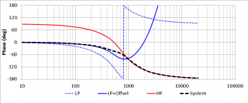
I made a quick sim because of the picture vs. 1K words thing.

It is a 4th order LR filter. The dotted line is phase, but since both phase shifts are aligned perfectly, they overlap and you can only see one.
It is a 4th order LR filter. The dotted line is phase, but since both phase shifts are aligned perfectly, they overlap and you can only see one.
In echo, here are group delays for LR24 and MTM 36, 1kHz:
An externally hosted image should be here but it was not working when we last tested it.
Linkwitz-Riley is not the be all and end all
I'm sorry, vacuphile, but it just ain't that easy (if only!) 🙂
Perfect phase matching (goal B in my original post) does not ensure time alignment (i.e. flat group delay = goal C in my original post). Hopefully jmbee's post helps to clarify this to you.
Hence the interest in "quasi-optimal" crossovers.
Marco
Yes Marco, but both drivers in a 2 way LR suffer from the same group delay. The only difference is that for the low driver this happens in the pass band, and for the high driver in the stop band. But, they are aligned, and that is the important thing. The only question is: is this group delay audible. I don't think so, in the plot above it is .5ms @ 1KHz. Plse Google for the research that has been done in the field of audibility of group delay, and you will see what I mean.
But, they are aligned, and that is the important thing. The only question is: is this group delay audible. I don't think so, in the plot above it is .5ms @ 1KHz. Plse Google for the research that has been done in the field of audibility of group delay, and you will see what I mean.
In LR4, low pass and high pass do have 360° phase shift, it's not equivalent to 0° for transient response of the sum, as you can see with simulation of LR4 654 Hz.
Imho, google knows nearly nothing solid about audibility of group delay thus you can experiment yourself easily with rePhase and a pc:
http://www.diyaudio.com/forums/multi-way/221434-rephase-loudspeaker-phase-linearization-eq-fir-filtering-tool.html
An externally hosted image should be here but it was not working when we last tested it.
Jmbee, yes, in LR4 both drivers go through the same 360 degrees rotation, with 180 degrees somewhere around the xover frequency. What is the problem with that? As you showed, the maximum group delay is .8 ms @ 450 Hz.
According to Blauert, I have his book on spatial hearing, but not the article Group delay distortions in electroacoustical systems | Browse - Journal of the Acoustical Society of America that explains research into threshold of the audibility of group delay, however I know the results. At 450 Hz, it is at least four times higher than the 0.8 ms in the example.
FIR filters can do away with this, but you exchange something inaudible (group delay) for something potentially audible (pre-ringing).
Experimenting is fun and I do not want to discourage anyone from doing so, but it is actually possible to learn from science published in the field. If you don't have the books, Google is a great learning tool.
I just wanted to report on my "reverse-angineering" studies about the TAD variant, and compare the two.
I have not had the chance of listening to otherwise identical systems employing the JMLC vs. the TAD crossover, but based on the simulations I SUSPECT that the TAD one just MIGHT sound better, that it all.
Hello,
You'll find here attached 2 screen copies. The first one shows the impulse reponse (IR) of the TAD TD2402 and the other one is the measurement of the IR of a 2 ways using nearly the same loudspeakers but with a JMLC crossover.
As you can see there is a 2nd pulse on the IR of the TAD TD2402 around 0.4ms (equivalent distance = 14 cm) fully explained by the group delay curve you shown to us.
Best regards from Paris, France
Jean-Michel Le Cléac'h
Attachments
According to Blauert, I have his book on spatial hearing, but not the article Group delay distortions in electroacoustical systems | Browse - Journal of the Acoustical Society of America that explains research into threshold of the audibility of group delay, however I know the results. At 450 Hz, it is at least four times higher than the 0.8 ms in the example.
Hello Vacuphile,
You don't use the Blauert criterium the right way it should.
For a given frequency if Blauert says x ms is the threshold, that means that with a delay between the 2 signals (e.g. pulses) larger than x, the 2 signals will be perceived as 2 separated signals.
Now if the delay is smaller than x then it signifies that only one "phase distorted" signal will be perceived.
(phase distortion being defined as for the "summation" signal having non constant group delay curve vs. frequency).
Best regards from Paris, France
Jean-Michel Le Cléac'h
Last edited:
Hello Jean-Michel,
"As you can see there is a 2nd pulse on the IR of the TAD TD2402 around 0.4ms"
Well, y wonder how jou got such a big second echo impulse !
My results taking in acount this filter , even +/- aproximative, are,
as you can see, quite different.
crd
"As you can see there is a 2nd pulse on the IR of the TAD TD2402 around 0.4ms"
Well, y wonder how jou got such a big second echo impulse !
My results taking in acount this filter , even +/- aproximative, are,
as you can see, quite different.
crd
An externally hosted image should be here but it was not working when we last tested it.
The Blauert paper shows results where the experimental subjects were asked to identify the "group delay distorted signals" withing groups of two, or three, discrete distorted and non-distorted signals. His conclusion is that trained listeners listening to the "most critical test signals" with "diotic earphone presentation" couldn’t detect group delay distortion below 0.5 mS. In the paper no mention is made of differentiation between coposite signals of two impulses
regards
Laurence
regards
Laurence
Hello Jean-Michel,
Well, y wonder how jou got such a big second echo impulse !
My results taking in acount this filter , even +/- aproximative, are,
as you can see, quite different.
Hello Jimbee,
The response of the TAD TD 2402 is taken from the firts link here (green frequency response curve) :
http://2.bp.blogspot.com/-HttNapLF7gA/TbjIKSwG56I/AAAAAAAACZA/Fi1_W0NDCnE/s1600/diffraction+horn.png
http://4.bp.blogspot.com/-3wCe1MaSJ...9%E5%85%A8%E9%A0%BB%E7%B7%9A%E6%80%A711ms.png
Both 2 measurements show that second peak,
May be it is due to some inner reflection in the TH4001 horn though.
Best regards from Paris, France
Jean-Michel Le Cléac'h
Last edited:
Hello Vacuphile,
You don't use the Blauert criterium the right way it should.
For a given frequency if Blauert says x ms is the threshold, that means that with a delay between the 2 signals (e.g. pulses) larger than x, the 2 signals will be perceived as 2 separated signals.
Now if the delay is smaller than x then it signifies that only one "phase distorted" signal will be perceived.
(phase distortion being defined as for the "summation" signal having non constant group delay curve vs. frequency).
Best regards from Paris, France
Jean-Michel Le Cléac'h
Jaen Michel, you are talking about what Haas found out.
More simulations, and possibly an improvement
Hello,
In response to some insightful comments made by Jean-Michel Le Cléac'h (here and on other French-language forums), I have made new simulations trying to further improve on the TAD crossover.
This is what I have come up with:
- Woofer low pass: 6th order Bessel at Fx * 1.25 (-6dB of attenuation at Fx)
- Tweeter high pass: 2nd order Butterworth at Fx * 1.3 (-6dB of attenuation at Fx)
- Offset = 0.4 * c / Fx
The result is even better phase match and a smoother Group Delay curve, still with a practical offset between Woofer and Tweeter.
Comments welcome.
Marco
Attachments

Hello,
Vacuphile : "At 450 Hz, it is at least four times higher than the 0.8 ms in the example."
That does'nt reflect the sensibility to phase distorsion , imho.
Do experiment with a soft like MacAudio Tool box, create a few sinus harmonics and change one of them from 0° to only 30°. Then 60° ect.
Mac Audio Function Generator Software Macintosh
No doubt you will hear changes resulting of variations of the wave form.
crd
Vacuphile : "At 450 Hz, it is at least four times higher than the 0.8 ms in the example."
That does'nt reflect the sensibility to phase distorsion , imho.
Do experiment with a soft like MacAudio Tool box, create a few sinus harmonics and change one of them from 0° to only 30°. Then 60° ect.
An externally hosted image should be here but it was not working when we last tested it.
Mac Audio Function Generator Software Macintosh
No doubt you will hear changes resulting of variations of the wave form.
crd
Hello,
In response to some insightful comments made by Jean-Michel Le Cléac'h (here and on other French-language forums), I have made new simulations trying to further improve on the TAD crossover.
This is what I have come up with:
- Woofer low pass: 6th order Bessel at Fx * 1.25 (-6dB of attenuation at Fx)
- Tweeter high pass: 2nd order Butterworth at Fx * 1.3 (-6dB of attenuation at Fx)
- Offset = 0.4 * c / Fx
The result is even better phase match and a smoother Group Delay curve, still with a practical offset between Woofer and Tweeter.
Comments welcome.
Marco
HI Marco
Is there any way i could contact you ?
i have few question regarding TAD 2402 and i am sure you would have a way to help me 🙂
thanks
phil
- Home
- Loudspeakers
- Multi-Way
- "Quasi-optimal" crossover for high-efficiency loudspeaker system