Welcome to the NVMOS Party BoyZ
HAHAHAHAHAaaa....
Hello Hugh,
You know GreG is an australian babe who design Killer amps.............but i dont want to die.......[GreG spare me at this time plzzz]😀 😀 😉
Ok Hugh, Now to the question......
The Full complementary are 100% symmetrical in Paper & Theory, but when it comes to practical real world stats..they suffer from Artefacts arising from asymmetry.....due to difference in degree of non -linearity
Lets Take the P-Channel , its Qgd[gate charge] is double than N-channel mosfet, so it simply requires more current at high frequency to function optimally which clearly affects the Slew...You cant have symmetric Slew rate....
The Transconductance of P-channel is again less as compared to N-channel.....affects the Gain
The Non - Linearities in both N-channel and P-channel are different in their aspects in these devices....The degree of Non-linearity in N-channel isn't as same as of P-channel, but if both devices at output are of Same polarity then you would have equal & similar set of non-linearities in the 2 Equal halves of wave, but in complementary the Degree of Non-linearity is not same , it varies and thus adds Coloration to the output signal...
The RDS of p-channel is again 2 Times that of N-channel, Affecting symmetric Clipping...& loading
N-Channel Vertical Mosfets are available in Various Specs to Suit the needs of amp designer....lot of Varieties....
VDS ranges from 50V to 1200V
ID ranges from 5A to 100A
Pd ranges from 65W to 700W
EXTREME SOA......also low Cost....
P-channel are very limited in variety...
I have Designed an amp with N-channel IGBT APT100GF60LVR
600V 100A 300W IGBT ,,....if you look at the SOA it is EXTREMELY BIG.......
Hope it serves you better,
regards,
K a n w a r
AKSA said:Greg, I agree!
Kanwar brings Bollywood exuberance to mosfet design, and knows a thing or two........
Half a volt from each rail into 2R, you say???????? WOW!!!
Kanwar, would you like to tell us why you think N-type quasi-comps are superior to full complementary designs?
Cheers,
Hugh
HAHAHAHAHAaaa....
Hello Hugh,
You know GreG is an australian babe who design Killer amps.............but i dont want to die.......[GreG spare me at this time plzzz]😀 😀 😉
Ok Hugh, Now to the question......
The Full complementary are 100% symmetrical in Paper & Theory, but when it comes to practical real world stats..they suffer from Artefacts arising from asymmetry.....due to difference in degree of non -linearity
Lets Take the P-Channel , its Qgd[gate charge] is double than N-channel mosfet, so it simply requires more current at high frequency to function optimally which clearly affects the Slew...You cant have symmetric Slew rate....
The Transconductance of P-channel is again less as compared to N-channel.....affects the Gain
The Non - Linearities in both N-channel and P-channel are different in their aspects in these devices....The degree of Non-linearity in N-channel isn't as same as of P-channel, but if both devices at output are of Same polarity then you would have equal & similar set of non-linearities in the 2 Equal halves of wave, but in complementary the Degree of Non-linearity is not same , it varies and thus adds Coloration to the output signal...
The RDS of p-channel is again 2 Times that of N-channel, Affecting symmetric Clipping...& loading
N-Channel Vertical Mosfets are available in Various Specs to Suit the needs of amp designer....lot of Varieties....
VDS ranges from 50V to 1200V
ID ranges from 5A to 100A
Pd ranges from 65W to 700W
EXTREME SOA......also low Cost....
P-channel are very limited in variety...
I have Designed an amp with N-channel IGBT APT100GF60LVR
600V 100A 300W IGBT ,,....if you look at the SOA it is EXTREMELY BIG.......
Hope it serves you better,
regards,
K a n w a r
Hi,
I know how to measure Vgs at a single current (Iq).
Can you explain the procedure, hopefully using simple equipment, to allow matching of both gate and transfer characteristics?
If this matching is done, can multiple output pairs be used without source resistors?
Do VFETs always need source resistors?
Is there a limit to how many parallel pairs (lateral and/or vertical) can be used without source resistors?
AndrewT said:Hi,
If this matching is done, can multiple output pairs be used without source resistors?
Do VFETs always need source resistors?
Is there a limit to how many parallel pairs (lateral and/or vertical) can be used without source resistors?
Hello AndrewT
Yes you can use them without Source resistors....only if their Vgs is matched within 10% tolerances
No these dont always need Source resistors, but they help in current sensing + force some sharing of current + Thermal Comp. + Local Feedback
As long as your Driver Stage is adequate to deliver the current to Mosfet Gates You can parallel them upto 100's virtually no limit, physically Yes , economically Yes...indeed
regards,
K a n w a r
The main pass element is a BJT. APT shows no reduction at any voltage up to the 600V maximum.
I don't believe their specs for SOA.
http://www.advancedpower.com/Communities/APT/Products/100GF60_B2R_LR.pdf
I don't believe their specs for SOA.
http://www.advancedpower.com/Communities/APT/Products/100GF60_B2R_LR.pdf
Sorry Andrew,
I also only match FETs by Vgs @ Iq. I mentioned "same characteristics" because a batch of the same matched N-channel FETs would have the same (within a error range) characteristics in comparison to a set of N-channel FETs and a set of P-channel FETs.
I guess Vgs measurements could be taken at 3 different Iq's to better match the FETs.
Source resistors take care of any differences between FETs even very small ones. A friend of mine runs matched IRF's without source resistors and the current sharing isn't that good (at idle anyway).
Cheers
djk said:The main pass element is a BJT. APT shows no reduction at any voltage up to the 600V maximum.
I don't believe their specs for SOA.
Hi DJK,
Would you Please ellaborate more ,i cant understand your statement....
What type of reduction is to be at 600V...The SOA curve clearly shows reduction at 600V, Mind it their IGBT's dont Suffer from Second Breakdown Voltage...and I have tested them....
These are new Generation IGBT's , dont compare them with older types...
regards,
K a n wa r
Attachments
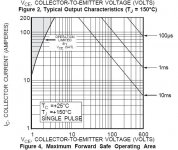
Most people claim FETs have no secondary breakdown, but this is wrong.
APT makes some special FETs for linear use that have better SOA than the IRF types designed for switching.
An APT type optimized for linear use that shows an SOA of 1.5KW on a non-repetative pulse, but only 100W at 500V on DC, going up to over 700W below 50V. This is secondary breakdown.
The IGBT parts will of course be worse. The curves are not shown for linear operation.
I have sent an e-mail to APT asking for linear test data, we will see what their reply is.
I got on to this thread very late - apology for late news.
Going back to the original question, I did some comparative analysis on quasi complementary (qc), compl. emitter follower and full complementary (fc) output stages using the same transistors, going up to 15th harmonic products. I thought that the results might be interesting, but find difficulty in attaching the particular format here.
But to summarise, I found that especially in the higher harmonic area, fc can be some 7 - 10 times "cleaner" than qc. (I accept that all know about the very detrimental effect high order harmonic distortion has on sound quality.) For that reason I was never sold on any other topology. The main reason for using qc appears to be the higher output obtainable, but using parallelled output transistors would solve that, even with its slight disadvantage.
If there is any interest in the above figures I can scan the document and try attach that.
Following on:
Sorry folks, I read the previous post in great hurry - your discussion is all about FETs. In that case arguments are different, naturally. Interesting posts.
Sorry folks, I read the previous post in great hurry - your discussion is all about FETs. In that case arguments are different, naturally. Interesting posts.
Hi Johan,
My experience as well that quasi- with BJTs produces a much greater high order spectrum. This is why I have produced full complementary amplifiers since the early '70's with MJ15003/4 as soon as they were released. As these albeit PA amps used CTP's (complementary feedback triples) it was easy to do a quasi for comparison - and the results were clearly audible even with the local feedback of the triple. The musos I was selling to could hear it too with their occupational ear overload so that was it.
I haven't bothered to repeat the tests using MOSFETs but I would welcome any FFTs from the quasi camp to c.f. mine posted on Simple Killer Amp here -
http://www.diyaudio.com/forums/showthread.php?postid=758931#post758931
Convert me. 😀
Cheers,
greg
Hi Greg,
Yes, priviledged to hear from you here. I just hit on the "Killer" thread and am still progressing through the several 100 posts - discovered somewhere into it who you were. (The title initially put me off from reading! When you market your excellent amplifier, kindly find a name more suited to your status!)
Although somewhat off-thread here, I have a collection of copies of your always most informatiove articles on file. At the time of your power rail contribution I shouted yeh!! Even earlier I wrote in a local periodical about this, giving oscillograms of the horror show visible on the B+ line of both tube and transistor amplifiers..... but nobody appeared to be unduly concerned.
I have up to now not done much in the power FET field and cannot opine there, but the BJT analyses left little room for doubt. As someone said a computer analysis uses perfect devices (although one can generate differences in models), but this difference is true for any application. (I also wonder how many folks discovered that the ubiquitous 0.22 something ohm emitter stabilising resistors are a source of high order harmonics - but that is another story.)
Thanks, Greg
Hi Johan,
Thanks for the support and pleased that you appreciated my Wireless World and Australian Hi Fi articles/contributions. Sadly, when it comes to power supply issues there are a quite a few Flat Earthers out there who would rather massively overbuild power supplies for some small improvement than improve the intrinsic design - which can often achieve 10 times the rejection for cents more c.f. a 10 times overbuilt power supply at massive $$$ and then gloat over the monstrosity of it all.
I only use sim for the basic structures, but being old school, I'm rather more at home measuring real devices and listening to real science based results. Real artefacts.
Good to hear from you.
Cheers,
Greg
Hi Johan,
D. Self hinted at the Re effect and just about came down on the side of always using 0r1 for these rather than the higher values.
When using multiple pairs, does the effective Re = actual resistor value or // resistor values. eg. one pair using 0r33 has an effective Re of 0r33, but three pairs each using 0r33 would be 0r11? Yes or not?
By the time we get down to four pairs of 0r22 = 0r055, is the distortion effect still measurable or audible?
Hi Cobra2,
I haven't built a quasi amp since 1973, when the MJ15003/4 were released and it was possible to build and compare complementary designs with the ubiquitous 2N3773 quasi's. Of course they were superior because the 3773's were so sloooow. But I did the listening tests as well using MJ15003's in quasi. The improvement was clearly audible to myself and the musos who bought the amps. We never looked back and went full complementary. I didn't have a FFT back in '74 - just a Sugden manual null THD set so was unable to analyse. However the higher harmonics of quasi outputs has been well documented over ensuing years, sufficient for my reassurance.
Of course availability of fast complementary output devices has opened up new design opportunities and topologies just not possible in quasi - such as my 150W Simple Killer Amp and it's 300W modulated bias cascode derivative -
http://www.diyaudio.com/forums/showthread.php?s=&threadid=67668
Neither of these use any source resistors - the elegant solution to Re distortion.
I note you emphasize SONIC qualities - these are the result of painstaking and enlightened attention to all the sources of intrusion on the signal and the designers ability to push back the boundaries. Revealing, however, can be too much for some showing the raw edges of the recording or ancilliary eqpt - that many would be happier with a sweet contrived 2HD or 3HD cover up.

Cheers,
Greg
I haven't built a quasi amp since 1973, when the MJ15003/4 were released and it was possible to build and compare complementary designs with the ubiquitous 2N3773 quasi's. Of course they were superior because the 3773's were so sloooow. But I did the listening tests as well using MJ15003's in quasi. The improvement was clearly audible to myself and the musos who bought the amps. We never looked back and went full complementary. I didn't have a FFT back in '74 - just a Sugden manual null THD set so was unable to analyse. However the higher harmonics of quasi outputs has been well documented over ensuing years, sufficient for my reassurance.
Of course availability of fast complementary output devices has opened up new design opportunities and topologies just not possible in quasi - such as my 150W Simple Killer Amp and it's 300W modulated bias cascode derivative -
http://www.diyaudio.com/forums/showthread.php?s=&threadid=67668
Neither of these use any source resistors - the elegant solution to Re distortion.
I note you emphasize SONIC qualities - these are the result of painstaking and enlightened attention to all the sources of intrusion on the signal and the designers ability to push back the boundaries. Revealing, however, can be too much for some showing the raw edges of the recording or ancilliary eqpt - that many would be happier with a sweet contrived 2HD or 3HD cover up.
Cheers,
Greg
Revealing is the way...
I want power-amps to be as revealing as possible...
- if I wanted to mask anything, I would do it at the source, (or find a chinese tube).
Arne K
I want power-amps to be as revealing as possible...
- if I wanted to mask anything, I would do it at the source, (or find a chinese tube).
Arne K
Hi Cobra2,
Well, in that case, and since you have an open plan design there, you would do well to choose a good example of modern complementary design that fits with your existing supply size.
Ideally I would suggest a FETcascode chip driven high PSRR nested/composite feedback design for a 'warts and all' experience. You may not like it.
I have real designs where THD is in < 0.0001%.
Cheers,
Greg
Quasi vs Fully com
Hello there all, just read the threads and I have just a few questions. Firstly Johan from Pretoria in South Africa, "hoe gaan dit boet". Good to hear from a fellow countryman.
1) Why would you build a quasi design which is unbalanced. The top device is always a unity gain voltage follower where the bottom device is a NOT but a common source amplifier.
2) Fets have much higher distortion than BJts and so masses of global feedback must be applied. We have built tens of thousands of quasi FET amps for the car stereo industry (Cheap to make as the drive ccts are simple and the FETs are cheap) but they sound terrible.
3) The same argument applies to quasi BJts. Fully comp BJts are so easy to work with and the various non linearities that exist are not that difficult to eliminate. We built the last THX series of Citation amplifiers for Harman Indistries (5.1 and 7.1) and through carefull design the amplifiers sound superb. Used Toshiba TO3Ps with a rather unique complemetary drive circuit. The drive circuit had it's own regulated power supplies and we are able to drive the speaker rail to within 1.8v of rail which is fine by me. The desire to drive the speaker rail to within 0.5 volt of the rails is meaningless - just lift the rails by an extra 2 volts and you make up this easily.
Stephen Mantz
Zed Audio Corp.
Los Angeles CA
www.zedaudio.com
www.dynotone.com
- Status
- Not open for further replies.
- Home
- Amplifiers
- Solid State
- Quasi-complimentary; pro / cons?