Hello Apex sir
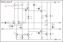
b550 amp circuit with op 2sc5200, +-35v is enuff for one pair of 5200.Help if any other changes required in circuit.And which PCB layout is correct, please mention,
Use PCB from post #294
No need to chahgeHallo all,
I need some help please.
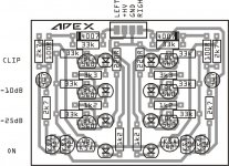
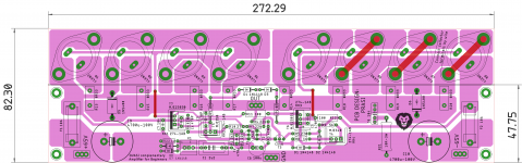
Ground goes to 0V of power supply.
HV+ goes to + rail of power supply.
Left /Right goes to speaker output of amplifier.
My supply rails are +-40VDC. Is there any changes that needs to be done ?🙂
Apex vu meter work with +/_40v power supply
Behrad, thanks for that. I see the original circuit uses MPSA42/92 transistors which are 300V vce transistors. Are they necessary when using 0-40VDC supply or can lower voltage transistors be used ?
Behrad, thanks for that. I see the original circuit uses MPSA42/92 transistors which are 300V vce transistors. Are they necessary when using 0-40VDC supply or can lower voltage transistors be used ?
U dont need to tra with lower vce voltage
Mpsa42/92 is ok for +/-40v power
Respectfully
Please Jan, post this in black&white for home etching.🙂Hallo all,
I need some help please.
Ground goes to 0V of power supply.
HV+ goes to + rail of power supply.
Left /Right goes to speaker output of amplifier.
My supply rails are +-40VDC. Is there any changes that needs to be done ?🙂
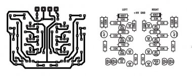
Apex do you perhaps have the flip side of the pcb layout. Will it be possible to use lower voltage transistors in the place of the MPSA42/92 on 40vdc rails ?🙂
I plan to modify my 10 stereo amplifiers which are made as per cosmic amplifier Circuits with 4pairs 2n3055 each channel. I personally rely much on metal casing transistors. with lots of regard vedmitra Sharma from city of Tajmahal.
Dear Vedmitra Sharma,
Cosmic amplifier Circuits are based on Cosmic LAB Stereomaster Series or Pro Power MK-II Swrites?
I hope you implied "Cosmic" based in Mumbai.
Regards
Aaron Nikhil
from a City of Charminar.😉
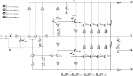
PCB with DC protection. 😱
what size have the PCB ?
is tested by someone?
i made quasi , sound is OK i can`t hear distortions
but 22K resistor is going too hot .
I move it to GND and now is perfect ....
apexaudio is that OK ?
but 22K resistor is going too hot .
I move it to GND and now is perfect ....
apexaudio is that OK ?
Attachments
Last edited:

Hello Mr. Mile,
Can this amp be made more stable and reliable to give about 200W-4ohm. Also with to-247/264 transistors.
regards
prasi
Here is slightly better version of pcb.
Attachments
Greetings to all .. what changes would have to be made to this amplifier to be able to use mosfet in its output? How would the schematic look?
Are the Gerbers available. Thanks!Here is slightly better version of pcb.
- Home
- Amplifiers
- Solid State
- QUASI Amplifier for Beginners