Hi all!
I need a schematic or project Mosfet guitar amplifier of 50...100W into 8 ohms, with IRFP240/IRFP9240.
Thanks and cheers!
I need a schematic or project Mosfet guitar amplifier of 50...100W into 8 ohms, with IRFP240/IRFP9240.
Thanks and cheers!
I have a project with a very robust mosfet-amp. But it is not too simple and I think it can be realizes with less semiconductors.
See if this one is good and simple enough :
60 Watt MosFet Audio Amplifier - RED - Page100
Have been using it for a long while w/o problem. got boards for it too.
BP
60 Watt MosFet Audio Amplifier - RED - Page100
Have been using it for a long while w/o problem. got boards for it too.
BP
See if this one is good and simple enough :
60 Watt MosFet Audio Amplifier - RED - Page100
Have been using it for a long while w/o problem. got boards for it too.
BP
I think that this schematic is dangerous - no thermal compensation and this is big problem. Second outputs are driven directly from the VAS witch is bad too.
I won't recommend this...
Schematic in post number 2 is much much better.
I have asked the original designer about this and he points out that the tracking was not necessary and would introduce over compensation. I had backed him up by building one and it is fine all along.
There is also Quasi's NMOS200 which has the thermal tracking but it is a quasi-complementary design.
There is also Quasi's NMOS200 which has the thermal tracking but it is a quasi-complementary design.
I have asked the original designer about this and he points out that the tracking was not necessary and would introduce over compensation.
Well this can't be true if VMOS devices like IRFP240/9240 are used will be true if LMOS devises are used like 2SK1058/2SJ162. HEXFET's have positive temperature coefficient and idle current will raise with temperature and this will eventually lead to thermal runaway. So I think thermal compensation is absolutely necessary when VMOS devices are used.
Mr Astankov you are right! It should be added to a solution for thermal stabilization of amplifiers.Well this can't be true if VMOS devices like IRFP240/9240 are used will be true if LMOS devises are used like 2SK1058/2SJ162. HEXFET's have positive temperature coefficient and idle current will raise with temperature and this will eventually lead to thermal runaway. So I think thermal compensation is absolutely necessary when VMOS devices are used.
Cheers!
This is another idea for a MOSFET guitar amp. In the diagram you can see the voltage and current at/through a simulated Speaker.
It has soft clipping and a short circuit protection.
An externally hosted image should be here but it was not working when we last tested it.
It has soft clipping and a short circuit protection.
If you can give a better schematic percent of the poor is seen!?This is another idea for a MOSFET guitar amp. In the diagram you can see the voltage and current at/through a simulated Speaker.
An externally hosted image should be here but it was not working when we last tested it.
It has soft clipping and a short circuit protection.
Thanks!
Small test of whether someone is interested. 😎
An externally hosted image should be here but it was not working when we last tested it.
Mosfet audio amplifier!?
Hi donpetru!
Which E-mail address to send the schematic?🙄
Best regards!
Hi donpetru!
Which E-mail address to send the schematic?🙄
Best regards!
Small test of whether someone is interested. 😎
An externally hosted image should be here but it was not working when we last tested it.
Hi moschfet!
Yes, I am interested in a small test!
Thanks
I think you've misunderstood me .
The poor representation of the schematic was the test..😀
No requests, no interest. Capito?
But if you want, you can build the circuit. Too large it is not 😉
The poor representation of the schematic was the test..😀
No requests, no interest. Capito?
But if you want, you can build the circuit. Too large it is not 😉
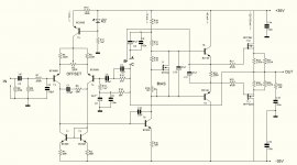
This schematic can be enhanced - design better CCS fir the input LTP and install drivers for the outputs. Now input capacitance of the MOSFET's is a big load to the VAS. Bias drivers at 30-40mA and will have a much better schematic.
On the picture is my home amp. Works perfect and sounds very well. Use it for an example.
Regards!
On the picture is my home amp. Works perfect and sounds very well. Use it for an example.
Regards!
Attachments
Questions abaut your schematics
Hi astankov!
I have a few questions about your schematics:
1. What connects the points A, B, C ?
2. In feedback mode that does not have any error (resistors: R13 and R14)?
3. Who replaced mosfet IRFP240/IRFP9240, with bipolar transistors 2SC5200/2SA1943 what changes are needed in the schematic?
Thanks and cheers!
Last edited:
Answering the questions:
1. I forgot to mention about this - when you connect A and C points bootstrap source is taken from the output and this is how the schematic works now it is something like "standard" mode. I was suggested that if I change the bootstrap source like to connect A and B points will have better results. Unfortunately never tried this and don't know what effect will have so I recommend to use the standard mode and connect A and C but you can try connecting A and B and see what will happen.
2. NFB schematic is correct it is obvious that is different than most people use. Values of the components marked with "*" depend from PSU voltage. Given values are for +/-35V PSU and if you want to use different supply they need to be recalculated.
3. Not sure what you ask but if you need to replace MOSFET's with bipolars like C5200/A1943 probably need to replace IRF530 with bipolar like BD139 and use different values for R16 and the trimpot R10. Also need to lower the gate resistors (they will become base resistors) to 1-2.2R and reduce value of C11 to 1uF. But all this is useless to be done - there are more and better schematics with BJT so you don't need to do that just use different schematic. Also I never tried to run this schematic with BJT so the given changes may result in problems and as I said before better use different scematic.
Regards!
Last edited:
Hi astankov,
I think your diagram is too complex and not yet sufficient.
One should not compare guitar amplifier with hi-fi amplifiers.
A guitar amplifier needs:
soft clipping
Short-circuit protection
poor damping
A current mirror and a driver for the Mosfets reduce the distortion. From about 0.05 to 0.01.
For what?
Guitarists call their sound clean, if the amplifier clipping 0.2%. But most of them do not like the cold sound of a PA amp.
OK I admit that never messed up with guitar stuff and don't know what the players prefer or what they don't. I use my schematic for home listening so probably is not good for guitar amp.
Regards!
Regards!
PCB for this amplifier
Thank you for your cooperation!🙂
Astankov, does the PCB can this amplifier?🙄This schematic can be enhanced - design better CCS fir the input LTP and install drivers for the outputs. Now input capacitance of the MOSFET's is a big load to the VAS. Bias drivers at 30-40mA and will have a much better schematic.
On the picture is my home amp. Works perfect and sounds very well. Use it for an example.
Regards!
Thank you for your cooperation!🙂
- Status
- Not open for further replies.
- Home
- Live Sound
- Instruments and Amps
- Quality MOSFET Guitar amplifier with IRFP240/IRFP9240