I quite agree. My only concern is that the soldering station in the local electronics shop is 300 Euros, and I know the trouble I have always had with big soldering joints with my soldering gun and the soldering pencil. I´ll see if I can get a used one, or maybe my daughter can get me one on the Internet without complaining too much.
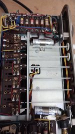
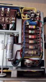
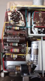
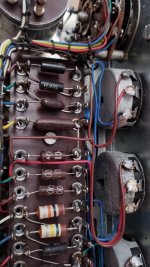
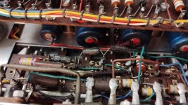
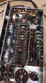
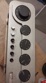
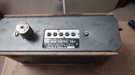
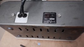
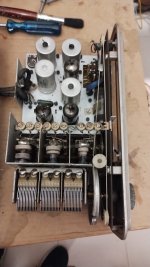
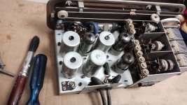
Attatched are pictures of the QCII unit. Possibly this one is not in such good nick...
BTW, the big, rectangular double TOC condenser in the Amp looks a bit daunting, but from what you say, it should be quite straight forward to change.
Attatched are pictures of the QCII unit. Possibly this one is not in such good nick...
BTW, the big, rectangular double TOC condenser in the Amp looks a bit daunting, but from what you say, it should be quite straight forward to change.
Attachments
-
 QCII-110.jpg166.9 KB · Views: 42
 -
 QCII-10.jpg209.5 KB · Views: 44
 -
 QCII-9.jpg135.5 KB · Views: 46
 -
 QCII-8.jpg227.1 KB · Views: 45
 -
 QCII-7.jpg178.6 KB · Views: 44
 -
 QCII-6.jpg222.3 KB · Views: 47
 -
 QCII-5.jpg224.8 KB · Views: 44
 -
 QCII-3.jpg217.6 KB · Views: 45
 -
 QCII-4.jpg224.8 KB · Views: 46
 -
 QCII-2.jpg112.7 KB · Views: 46
 -
 QCII-1.jpg124.6 KB · Views: 46
Last edited:
Hi Anatech!
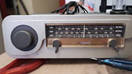
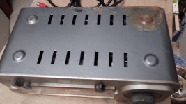
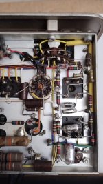
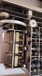
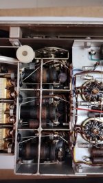
... and now for the AM-II Tuner pics. This one has rust on its feet too, just under the variable tuning condenser, but I think the water just dibbled down the sides inside and only accumulated in a puddle beneath, on the metal shelf where it was.
I wonder if it´s worth while setting up and running the set again, but with the Tuner open, to see if the few valves in here glow pleasingly...
Well, now I must proceed with drawings and lists for each of the units. I have the schematics of the three of them, but of course, the position of the components there is nowhere near to where they are in the pictures. But... I have already identified the ones from the Amplifier.😎
If scanning and attaching the schematics of the three will be interesting for anyone, let me know, otherwise perhaps it´s boring so I won´t bother.
Cheers,
Aleatorylamp
Attachments

Last edited:
Hi Aleatorylamp,
Deal with the amplifiers first.
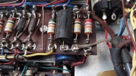
This is before and after on the last one I did. You can probably figure out how I mounted the capacitor. Notice the messed up job I had to clean up. On the left side you'll see a metal plate with an RCA jack that was installed. Thick metal, I was able to tap it so it is a solid mount. You'll be leaving that area stock, the way it is.
Deal with the amplifiers first.
This is before and after on the last one I did. You can probably figure out how I mounted the capacitor. Notice the messed up job I had to clean up. On the left side you'll see a metal plate with an RCA jack that was installed. Thick metal, I was able to tap it so it is a solid mount. You'll be leaving that area stock, the way it is.
Attachments


Hi Anatech,
Yes, that was my plan, first the amplifier (there´s only one), then the QCII, and finally the AMII.
A very smart and clean looking job you did on your last one!
It gives me an idea about what mine´s going to look like. Thanks for the tips!
I was looking into the online catalogue of the local electronics components dealer here, and became a bit worried because nothing in there looked like anything contained in my present set, but now I see what more modern components are going to look like. Actually, I only knew about the tiny components I use for the little Arduino gizmos I put together - no heavy duty stuff at all. This is quite a different kettle of fish.
I would take that rusted bottom plate, in fact both of them and the two cases for the preamp and tuner too, to a powder coater and have them redone. The colour is Rover Grey.
You’re in luck with the tuner, it doesn’t have those red Hunts caps. Measure all the resistors connected to the HF and replace any that are > 20% out. Nothing else. Make sure the tuning capacitor is clean and dry.
You’re in luck with the tuner, it doesn’t have those red Hunts caps. Measure all the resistors connected to the HF and replace any that are > 20% out. Nothing else. Make sure the tuning capacitor is clean and dry.
Hi Aleatorylamp,
Yes, I was hoping it would give you a clue. Mostly how to mount the new filter capacitor. You can also see the way modern parts look. You can do as good a job as I did. I didn't go crazy on this one.
Keep voltage ratings in mind. That goes for resistors and capacitors.
Yes, I was hoping it would give you a clue. Mostly how to mount the new filter capacitor. You can also see the way modern parts look. You can do as good a job as I did. I didn't go crazy on this one.
Keep voltage ratings in mind. That goes for resistors and capacitors.
Oops, I mean the HT of course.Measure all the resistors connected to the HF
The FM tuner and potentially the control unit are not worth the expended effort and expense, IMO. The amplifier is trivial to restore in comparison to them, and they do not really work so well with modern music sources.
The amplifier (there is just one?) looks to be an early example since there are visible spot welds on the cover of the OPT, so you could check Keith Snooks page here and see if you have the old OPT.

I have a pair with one old OPT and one new, and I don't hear a difference, but useful to know since there are some alternate winding options with the new OPT.
Something I discovered the hard way is that the tag boards used for the driver circuit have quite brittle tags, so the kick from a desoldering tool can snap them off.
The nuts and bolts look like they will be simple to replace, but unfortunately they are a UK size '4BA', and not so easy to find replacements that look right.
Otherwise they all look like they got off lightly from the water damage! A quad enthusiast would recognise your quads as being totally original, unrestored, and they do have a premium value now because of that. You might even be able to sell them as they are now for the same price as buying a working restored example.
The amplifier (there is just one?) looks to be an early example since there are visible spot welds on the cover of the OPT, so you could check Keith Snooks page here and see if you have the old OPT.
I have a pair with one old OPT and one new, and I don't hear a difference, but useful to know since there are some alternate winding options with the new OPT.
Something I discovered the hard way is that the tag boards used for the driver circuit have quite brittle tags, so the kick from a desoldering tool can snap them off.
The nuts and bolts look like they will be simple to replace, but unfortunately they are a UK size '4BA', and not so easy to find replacements that look right.
Otherwise they all look like they got off lightly from the water damage! A quad enthusiast would recognise your quads as being totally original, unrestored, and they do have a premium value now because of that. You might even be able to sell them as they are now for the same price as buying a working restored example.
Last edited:
Hi ejp,
Thanks for your message. I was in fact just going to ask is a l vaccuum cleaner to get off the dust and loose rust, a slightly abrasive dish-washing sponge and a little ferrous sulphate solution (Oxino) would be enough to get rid of/stop further oxidation on the chasis, and leave it at that for originality`s sake...
Let´s see what the story is with the tuner. Interesting, your observations and deductions! I´ll follow your suggestions as soon as it is the tuner´s turn for fixing.
Hi Anatech,
Yes indeed!!
I´ve just put all the valves into a cardboard box with a lid, with three dry dish-towels inside for protection, and marked the places they go on a drawing, as not all the lablels on the chasis are intact anymore. Now I`ll proceed with the innards drawing for my imminent visit to the local electronics shop.
What fun!😀
Hi OldHector,
Thanks for your useful comments!
Serial number 12401 is the one for the QUADII Main Amplifier from Huntington, England.
Sorry, "There is only one" referred to the fact that there isn´t pair as used in a stereo outfit. Of course, there are 2, the second being the pre-amp in the QC-II.
Silly of me.
In order to keep everything original, I thought of just cleaning the screws that are rusted, sand them slightly and applying prussic acid to stop further rusting.
With successful restoration, I could use this mono system as an amplifier for my Arduino Synthesizer projects (copied from others, not own creations), perhaps, although of course, selling it would be a lucrative option, both now and/or later, if it were to be more fun selling it that actually using it. I have gone off the idea of giving it away....
Hi Together,
I was looking through all the documents that came with the set when it was given to me in the early 90´s, and there is some correspondence in 1980 between the manufacturer and the owner due to a shorted speaker, with symptoms described as a cyclic click and hiss, which apparently the original owner never understood, and which I also got, but disappeared as soon as I replaced the speaker.
Sadly, during the long storage, the speaker membrane and parts of the makeshift box I prepared it was pasture for termites that migrated over from a stored wicker chair. Fortunately termites did not have an appetite for anything else!
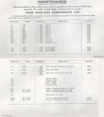
Anyway, this correspondence also included extra schematics. instructions and parts lists of all three units, so there may be variations to the originals, compared to the schematics scans attached herewith, and definitely to the parts list scan. The scans are for the event they could be of interest.
Anyway, from what Anatech says, I gather I can measure the resistor values before dismounting them...
I was looking through all the documents that came with the set when it was given to me in the early 90´s, and there is some correspondence in 1980 between the manufacturer and the owner due to a shorted speaker, with symptoms described as a cyclic click and hiss, which apparently the original owner never understood, and which I also got, but disappeared as soon as I replaced the speaker.
Sadly, during the long storage, the speaker membrane and parts of the makeshift box I prepared it was pasture for termites that migrated over from a stored wicker chair. Fortunately termites did not have an appetite for anything else!
Anyway, this correspondence also included extra schematics. instructions and parts lists of all three units, so there may be variations to the originals, compared to the schematics scans attached herewith, and definitely to the parts list scan. The scans are for the event they could be of interest.
Anyway, from what Anatech says, I gather I can measure the resistor values before dismounting them...
Attachments

Last edited:
Yes, it appears to be old, old, old!
Sorry for the silly question I was meaning to ask .... What is an OPT? - Perhaps, or rather probably, Output Transformer, I suppose.
If the OPT is different, will it matter?
This one appears to take speakers of 5 to 8 Ohms (no more modern 4-Ohm stuff!).
Someone seems to have penciled something in at the OPT on the schematics. If that applies to this model is another matter, but maybe it was the original owner who was correcting something, or the manufacturer, who sent him the schematics in 1980...
(There are also schematics and parts lists for the QCII and AMII, but we´ll come to that when the main amp is finished).
Last edited:
Yep, output transformer. The load on the secondary is reflected to the primary, connected to the anodes of the output tubes. They have an optimum 'load', so the pencil marks show an alternate 'strapping' on the binding posts on the OPT to reflect the correct load.
Patrick Turner (RIP), a fellow antipodean, goes into a lot of detail about the reflected loads and the response curves on his site, Patrick Turner: Quad2 mods
If you have the older opt it will have the letters 'A' to 'H' (I think), and it is slightly different to do the wiring change.
Patrick Turner (RIP), a fellow antipodean, goes into a lot of detail about the reflected loads and the response curves on his site, Patrick Turner: Quad2 mods
If you have the older opt it will have the letters 'A' to 'H' (I think), and it is slightly different to do the wiring change.
Thanks, OldHector!
I´ll have to investigate this and see what it could imply for me to do...
Incidentally, I just thought of a cunning plan:
Cut the old resistors condensers out wires without de-soldering the wires from the original soldering point, and solder the new components onto the wire stubs that are left. That way the original soldering points are preserved, and will not complicate matters trying to unsolder these large soldering points...
Or is this like in the Blackadder Series:
Baldrick: "Sir, Sir, I have a cunning plan, Sir!"
Blackadder: "Baldrick, will you run into my fist please?"
Cheers,
Aleatorylamp
You won’t have any problem removing the old components. They’re not wrapped around the terminals, just poked through the holes and soldered. Cut the leads and then remove each side.
The AM tuner (not FM) has some rarity value, as dies the preamp, which is a pretty good solution for 78s and pre-1954 LPs.
The AM tuner (not FM) has some rarity value, as dies the preamp, which is a pretty good solution for 78s and pre-1954 LPs.
I would definitely restore those components. They are what they are. Having them operating properly is the best thing you can do. Performing a bunch of modifications wouldn't be a path I would follow.
The place to buy new BA fasteners (of any size) is suppliers who cater to model engineers.The nuts and bolts look like they will be simple to replace, but unfortunately they are a UK size '4BA', and not so easy to find replacements that look right.
Otherwise they all look like they got off lightly from the water damage! A quad enthusiast would recognise your quads as being totally original, unrestored, and they do have a premium value now because of that. You might even be able to sell them as they are now for the same price as buying a working restored example.
I would agree with all the other comments about restoration. The moment you do any work, the value to a collector drops. But if you actually want to use the amplifier, it needs attention. Rather than drill extra holes in the chassis to replace that TCC capacitor, I'd bolt a 6mm thick plate on the inside of the chassis using the original screws, but drill and tap that plate to take the new part. That way, it can all be put back to original if required. The QCII control unit is pretty dreadful. Perhaps more to the point, although it will probably contain dried-out electrolytic capacitors and carbon resistors whose value has gone high, it will certainly contain switches having corroded contacts. It is possible to take switches apart to clean their contacts, but it isn't an easy job by any means. Frankly, I wouldn't bother. But you might want to make it all work for nostalgia, and I won't argue with that.
Hi Anatech, Hi ejp,
I didn´t know the AM-II and QC-II were so rare, but if so, better so!!
I thought it was a standard combination for a non-stereo equipment... The gramophone impedance I´m sure is for a crystal needle.
It had also come to my mind to think about changes so as to be able to tune FM, but I´m sure it would involve quite complicated coil issues and then the scale would be quite off - 88-108 Mhz, and then, which of the existing SW or LW would you eliminate?
I agree it´s best just to get them going without further complications.
Hi OldHector,
I´m afraid Patrick Turner´s site is all a bit over my head...
The A to H letters on the OPT would be inside the biggest metal box, I gather, which I was trying to avoid opening as it would involve bending some wiring to get at one of the screws... It was working OK 20 years ago, so I think it may not need attention, as the set wasn´t connected when it got wet?
- Home
- Amplifiers
- Tubes / Valves
- QUAD II mono amp/control unit/tuner (old model-1960)