Forget trying to modify an AM tuner to FM. Completely different, I'm afraid. Looks like you're down to fixing the power amplifier as suggested by anatech.

Hi EC8010,
The screw heads and holes are completely hidden from the outside when done as I suggested. If someone were to later install the box type capacitor, all changes would be completely invisible. I try to balance effort vs cost and reliability when I work.
The screw heads and holes are completely hidden from the outside when done as I suggested. If someone were to later install the box type capacitor, all changes would be completely invisible. I try to balance effort vs cost and reliability when I work.
Yes indeed, I´d already discarded FM just after thinking about it for 30 seconds.... no problem!Forget trying to modify an AM tuner to FM. Completely different, I'm afraid. Looks like you're down to fixing the power amplifier as suggested by anatech.
I´ve just dismounted the box TCC Dual condenser, and I think I´ll refrain from opening it and to as Anatech suggests in his attached picture of the new dual cap.
Anyway, I´ve figured out all the resistor codes, and printed the components list out for the visit to the electronics dealer tomorrow.
Let´s see if I can get all of these (not many) parts!
Cheers!
Attachments
Last edited:
None taken. Your method is certainly neater, but for most people (including me) it would be a real project!
I avoid drilling holes without good reason. If I have to, I do my best to keep them hidden. I like your idea a lot, but my time is chargeable. I don't like wasting people's money.
I avoid drilling holes without good reason. If I have to, I do my best to keep them hidden. I like your idea a lot, but my time is chargeable. I don't like wasting people's money.
One of the tools I made a few years ago is a tapping fixture. It started life as a hand-cranked pillar drill that I bought at a car boot sale. In place of drilling chuck etc, it now has a simple vertical shaft with a collet chuck to take taps and a T-bar at the top to twirl them. The huge significance is that when I twirl a tap into a hole, it goes in with zero wobble and no sideways stress that could snap a tap. I have cheerfully tapped M2 blind using this tool. Best tool I ever made. And I have a bandsaw to neatly cut the 6mm aluminium. Lubricate aluminium when cutting with methylated spirits (I think it's called denatured alcohol across the Atlantic). With the right tools, any job is easy...
Hi Anatech,
I was just looking at your "Complete.jpg" photo in post #23: The big new blue 32 microfarad capacitator seems to have two connectors that are obviously different from the old TCC Dual box-type cap with three connectors, i.e.
+P, with a single wire connected,
+PE, with two wires connected, and
-C, the common negative in the middle, also with two wires connected.
From what I can see, the new cap has two connectors, one with 3 wires, and one with two. It looks like the single wire goes to the positive terminal of the new cap, so the negative terminal must get the two negative wires previously on -C, the old common negative. Then, the remaining two wires previously connected to +PE are seemingly now also connected to the positive terminal of the new cap. Am I right?
Hi EC8010,
Thanks for your counsel on the QCII components. I will take that into account!
It isn’t necessary. The contacts are exposed and easily cleaned with switch lubricant.It is possible to take switches apart to clean their contacts, but it isn't an easy job
It depends on which adapter you have. The most common one is for MM.The gramophone impedance I´m sure is for a crystal needle.
Impossible. Completely and utterly. Forget it. If you want FM, buy the Quad FM tuner that goes with this set. But it will need work.It had also come to my mind to think about changes so as to be able to tune FM,
No, they are next to the terminals on the OPT.The A to H letters on the OPT would be inside the biggest metal box, I gather,
There is no reason whatsoever to replace the dual cap unless it’s faulty. The main failure mode is a short to ground.
Last edited:
Hi aleatorylamp,
The common terminal is hidden under the others. It was connected exactly the way the originals were.
The two capacitor sections have a common terminal as the original does. I just desoldered the wires from the ring terminals and connected the wires directly to the terminals on the new capacitor. I have seen people unscrew the ring terminals and solder the entire mess to the new capacitor(s), then glue that mess down. Lazy as heck!
Hi ejp,
I'll disagree with you on the reliability of those older capacitor assemblies. I see them go open often enough or reduced capacitance with high DA. If the capacitor measures fine for both capacitance and DA, I'll leave it. If one of a pair needs a new capacitor, they both get one. That keeps them the same as the new capacitors have higher capacitance. So we agree on the defective part, but I measure them more closely to avoid near future failures.
Yes indeed, I´d already discarded FM just after thinking about it for 30 seconds.... no problem!
Hi ejp,Impossible. Completely and utterly. Forget it. If you want FM, buy the Quad FM tuner that goes with this set. But it will need work.
... not to worry, in my post #44 I said I´d already forgotten about that.
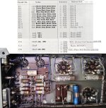
Well... Next to these terminals, there is: A pair marked as 6.3 v., another pair marked as 5 v, and a third pair marked as HT on the inboard side, and on the other side at the end with the 110 V selector and the fuse, there´s E, COM, 130v, 115v, and 110v.No, they are next to the terminals on the OPT.
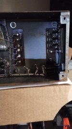
I began unscrewing the big OPT box to have a look for the letters inside, but soon left that alone as it became clear that all the terminals were soldered to the OPT, and the OPT was screwed to the box... Slap on my fingers with a ruler!
Attachments
Last edited:
Hi Anatech,
Thanks for the clarification! So the 3 contacts on the new capacitator are the same - no problem then.
I was just thinking of checking the components in the QCII first, before going to the electronics shop, so as to include things needed for that one too.
This way I can check if both the QUAD II Amp and the QCII Pre-Amp control unit work once repairs are done, as both units seem to be interdependent.
If you have a Bluetooth receiver, then you can just connect that to the Quad amp. They work very well.
The amp will be a simpler proposition to update. Part of the beauty of the Quad is the way it is laid out, so if you have good pictures and perform a like-for-like restoration, then it is not so much effort to get the amp going, and then you have nice music to listen to while you work on the control unit.
The amp will be a simpler proposition to update. Part of the beauty of the Quad is the way it is laid out, so if you have good pictures and perform a like-for-like restoration, then it is not so much effort to get the amp going, and then you have nice music to listen to while you work on the control unit.
That’s the power transformer (PTX). The letters refer to the output transformer (OTX) at the other end. No need to remove either of them.Next to these terminals, there is: A pair marked as 6.3 v., another pair marked as 5 v, and a third pair marked as HT on the inboard side, and on the other side at the end with the 110 V selector and the fuse, there´s E, COM, 130v, 115v, and 110v.
I didn’t say anything about their reliability. I said there is no reason to replaced them unless defective, and in my experience that is not common. I also didn’t say anything about how I test them. You’re jumping to conclusions in both cases.I'll disagree with you on the reliability of those older capacitor assemblies
Hi ejp,That’s the power transformer (PTX). The letters refer to the output transformer (OTX) at the other end. No need to remove either of them.
Oh wow! Sorry about that. I didn´t see it, did I? ...and, I didn´t really know what OPT or OTX was either.
Anyway, I just saw the letters pretty well hidden under the resistor rack board. They are: P, Q, R, S, T, U, V, W, next row X, Y, and Z.
Hi OldHector,
Then, all capacitators do look pristine, but who knows... Now that I´m at it, I´ll change them as well. Pity about the old stuff if it´s still good, but I don´t want to have to open the thing again.
Regarding Bluetooth, I wouldn´t know how that works... too modern for me. To test the Amp, maybe an old cassette-recorder loudspeaker output at low volume perhaps, or the earphone output maybe? I´d have to figure out the connections though, because all the input seems to be managed by the QCII.
That´s the way it looks. The two 680K resistors won´t move the needle, and the 470 ohm one is cracked., and my voltmeter´s x10k position is broken, but the needle moves ever so slightly for the 1M and 1.5M resistors. The others seem OK, but I´m changing the lot.The amp will be a simpler proposition to update.
Then, all capacitators do look pristine, but who knows... Now that I´m at it, I´ll change them as well. Pity about the old stuff if it´s still good, but I don´t want to have to open the thing again.
Regarding Bluetooth, I wouldn´t know how that works... too modern for me. To test the Amp, maybe an old cassette-recorder loudspeaker output at low volume perhaps, or the earphone output maybe? I´d have to figure out the connections though, because all the input seems to be managed by the QCII.
Last edited:
Hi ejp,
Just clarifying. In my experience, most of those filter caps have problems. That's all.
Hi aleatorylamp,
Today's parts are a lot better than the old ones, more stable for one. Capacitors, we have come a long way, especially where leakage currents are concerned.
So for the amplifier circuits, go with the higher power Metal Film resistors (1 watt minimum, 2 watts if you need the higher voltage rating). Check the breakdown ratings in the data sheet before you buy. You'll probably end up with mostly 1% values, for the power supply dropping, Metal Oxide are fine, 5% values. Small capacitors. Polypropylene. Higher voltage ratings are fine and this type has very low distortion. May as well. For the other electrolytic capacitor, and axial rated at higher voltage. They are better capacitors and higher voltage makes them closer to the original size of part. 85°C parts are perfectly fine in your amplifier. 105°C parts are sometimes not as good, so do not assume they are automatically a better part.
This normally means you order from a web site. Most shops do not have the information you want, or the selection. In the old days (when I was younger) we had carbon composition resistors and wirewound. That was about it. A 1/2 watt carbon composition resistor was rated for 500V. You'll be hard pressed to find a modern 1/2 watt resistor rated for 500V, I'm sure they exist and some members will pull out example, but this shouldn't be expected and it is not normal.
Hello Anatech,
Thanks for the summary of what to get for the QuadII´s new parts.
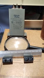
I went to my local store, and they are preparing the order for the Amp resistors and capacitators. They had no big round dual ones for the 32 mu substitution of the 16 mu ones, in fact no dual ones at all. Their supplier´s manufacturer apparently doesn´t make them and they are not allowed to order on the internet.
They only had 2 single electrolytic 33 mu (450v, -40º + 105º) condensers, 2.5 cm long and 1.5 cm wide. They only cost 90 cents each. See comparison photo. If these won´t do, given the seemingly good condition of the original, possibly that can stay onboard...
Regarding the resistors, they are getting me 2W ones where possible, or else 1W, for tomorrow, and also the other 4 capacitators. It won´t be expensive.
I got fed up with difficult readings, and got myself a digital multimeter. I had already de-soldered one leg of all old resistors to get better readings, and it seems that now all of them give a reading with less than 20% tolerance, including the cracked one, but I´ll replace the lot.
I am in fact more inclined to think that the problem rather lies in the control unit, or else in the tuner.
Incidentally my soldering gun is a 100W one, so it is quite good for the job. A soldering station is economically not viable for the moment, I´m afraid.
Thanks for the summary of what to get for the QuadII´s new parts.
I went to my local store, and they are preparing the order for the Amp resistors and capacitators. They had no big round dual ones for the 32 mu substitution of the 16 mu ones, in fact no dual ones at all. Their supplier´s manufacturer apparently doesn´t make them and they are not allowed to order on the internet.
They only had 2 single electrolytic 33 mu (450v, -40º + 105º) condensers, 2.5 cm long and 1.5 cm wide. They only cost 90 cents each. See comparison photo. If these won´t do, given the seemingly good condition of the original, possibly that can stay onboard...
Regarding the resistors, they are getting me 2W ones where possible, or else 1W, for tomorrow, and also the other 4 capacitators. It won´t be expensive.
I got fed up with difficult readings, and got myself a digital multimeter. I had already de-soldered one leg of all old resistors to get better readings, and it seems that now all of them give a reading with less than 20% tolerance, including the cracked one, but I´ll replace the lot.
I am in fact more inclined to think that the problem rather lies in the control unit, or else in the tuner.
Incidentally my soldering gun is a 100W one, so it is quite good for the job. A soldering station is economically not viable for the moment, I´m afraid.
Attachments
Last edited:
No, get the dual caps. Order them. If I saw those in a unit, they are on the estimate for replacement.
There is only one way to do things. The right way. If you don't have data sheets on the resistors, order from a supplier. Simple. No longer can you assume the parts people know what they are doing like the old days.
There is only one way to do things. The right way. If you don't have data sheets on the resistors, order from a supplier. Simple. No longer can you assume the parts people know what they are doing like the old days.
- Home
- Amplifiers
- Tubes / Valves
- QUAD II mono amp/control unit/tuner (old model-1960)