That's what QUAD does. But their custom transformer is so good that they don't need the buffer stage 😎
Jan
Jan

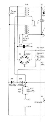
I think I have mentioned I'm modifying a '63 to run on external transformers, in order to easily switch between those step-ups and a direct drive amp.
Since I also run the thing with seperate subs through a DSP'ed multichannel DAC, I omitted both the 1R5 (R15) resistor and the parallel 220uF cap (C25).
To my big surprise, at the first test play, both of the1R65 (R1 ab and R2 ab) resistors in series of the xformer primary popped! (These were the original flat substrate resistors 2 x 3R3 in parallel). WTF??
Anybody have an explanation for that? Are the 1R5 // 220u so critical?
Jan
Attachments
Last edited:
The 1R5 prevents large currents to flow into the Xformer at very low frequencies where saturation turns the transformer into a short circuit.
Obviously you must have had those very low frequencies because in my Quads I have shorted the 1R5 for more than 40 years and never had any problem.
Hans
Obviously you must have had those very low frequencies because in my Quads I have shorted the 1R5 for more than 40 years and never had any problem.
Hans
Those resistors are quite reliable in my experience. But I always have the 15ohm and 220uf (with film bypass) in place.
You have low frequency energy, and a lot of it, or maybe some sort of DC offset?
Sheldon
You have low frequency energy, and a lot of it, or maybe some sort of DC offset?
Sheldon
Yes, it does make sense, but I have no idea what it could have been.
Start-up pulse from the Purifi class D amps?
No appreciable DC offset.
There is about 2 feet of HV wiring from the transformer secondaries to the stators, I wouldn't think that could cause oscillations?
Jan
Start-up pulse from the Purifi class D amps?
No appreciable DC offset.
There is about 2 feet of HV wiring from the transformer secondaries to the stators, I wouldn't think that could cause oscillations?
Jan
Maybe some hf switching frequency leftovers present at the output of the amps? C14 will be a straight short at hf.
Hf would have been fully conducted by the 220uF cap as well, so either DC or a very low frequency must have caused this problem.
Hans
Hans
Jan,
Did you ever had the 1R5//220uF still installed with your external xformer setup and if so what happened than?
Hans
Did you ever had the 1R5//220uF still installed with your external xformer setup and if so what happened than?
Hans
C14 and the rest of that subsystem is not present.
I didn't have the 1.5R//220u on this system. It is in a non-modified speaker, driven by the same amp, and never had the problem there.
I should also mention that the system played fine at low level during initial testing.
I then turned up the level and - poof!
Jan
I didn't have the 1.5R//220u on this system. It is in a non-modified speaker, driven by the same amp, and never had the problem there.
I should also mention that the system played fine at low level during initial testing.
I then turned up the level and - poof!
Jan
I'd rather not use the 200uF as that would either not be very linear or be very expensive, depending on the type.
With everything DSP'd I don't need it I guess, but I probably better put the 1.5R back in!
(The 1.5R//220u has an fc of about 1.2kHz if I did my sums right).
Jan
With everything DSP'd I don't need it I guess, but I probably better put the 1.5R back in!
(The 1.5R//220u has an fc of about 1.2kHz if I did my sums right).
Jan
C14 is part of the impedance shaping circuit, so you really need that one.
Without, imepance at around 20Khz will be very low.
Hans
Without, imepance at around 20Khz will be very low.
Hans
Thanks Hans, I missed that! I thought it was part of the limiting circuit...
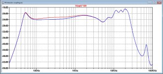
Do you mean 'impedance will be very high' - I did see rising freq resp without this cap.
Jan
Do you mean 'impedance will be very high' - I did see rising freq resp without this cap.
Jan
Last edited:
The resistor without the cap isn't a great solution either, as the combined impedance isn't anywhere near flat
Sheldon

Sheldon
Actually, without the cap the electrical response on the stators rises above 10k.
I'm rolling off the response in the direct drive amp.
So without that cap I may be able to delete that DSP rolloff.
Or partly.
Jan
response
I'm rolling off the response in the direct drive amp.
So without that cap I may be able to delete that DSP rolloff.
Or partly.
Jan
response
Last edited:
Looking at it from an attenueation point seen from the amp to the speaker.
Assuming that the speaker is nominal 4 ohms (just to get an idea), at DC the attenuation of the output signal is 4 ohms/ 5.5 ohms or about -3dB.
For a high frequency where the cap shorts the 1.5 ohm, the attenuation is 0dB.
So the most the cap does is +3dB at 20kHz.
I can easily take care of that.
Jan
That's a good point, there is some phase shift associated with it too. Not sure it matters at all, but if it did, you could also take care of it with your DSP as well.
Sheldon
Sheldon
Oh good, this excellent thread now touches on something I've always wondered - just what is that RC combo, there, for?
Why add a high-pass, there?
In the various 63 & later implementations, each half of the audio step-up transformer has 3R3 in series with it, so that should address instability / motorboating issues - perhaps more-needed when valve amps were Quad's Thing, or even the Quad 303.
I've always had it filed in the all-pass filter of '...Peter Baxandall must have had a reason why' bucket, even to the point of : perhaps its only ever been carried-on by Quad in the same vein: 'there must be a reason, even if we don't know why any more.'
Some sort of 'balance' / fix for increasing directivity vs. panel width is the best case I can imagine; but haven't tried bypassing it on mine (989s) & measure in-room to test this.
I'd welcome all thoughts on this!
- Home
- Loudspeakers
- Planars & Exotics
- QUAD 63 (and later) Delay Line Inductors