Hello,
I just finished to rework the PCB for a Quad 405 based on the schematics of Keith Snook DCD Mod-3. I used a PCB M12565 iss. 7 (so without Tr4) as starting point and reworked it to meet the modified schematics and sizes of my components.
I reintroduced N1 and N2 in schematics but without C18, C19 wich could be soldered on N1, N2 (if are used).
The size of the fuse holder might not be good, it has to be modified. There are three connections that have to be made with a small wire (the ones wich have grey pads).
If you have some ideas how should I improve the design feel free to write it as I plan to make it in 1-2 weeks.
Regards,
Zsolt
p.s. Some transistors in the schematics differ as I couldn't find them among the libraries, so don't write for this issue!!!
Attachments
Project
I forgot... if somebody is interested I can send the project files. It's made with Altium DXP.
I forgot... if somebody is interested I can send the project files. It's made with Altium DXP.
Hi,
it looks pretty good to me, much neater than my efforts to date! You might want to make a bit more space for R30 & R31 though. They dissipate just over 1 watt each when the amp is idling and get quite hot. I use 3 or 5 watt resistors for these and try to mount them well above the PCB. By the way, what are you using for the inductors, or are you winding your own?
Andy
Reworked version
Hi,
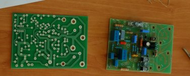
I reworked the PCB and kept only the components from DCD-Mod3.
My goal was to keep the tracks in the operational feedback and in the bridge as short as possible and to widen the gnd, earth and high current tracks. I've added Tr3 + R18 in this final version but in case of instability I will replace them with a wire link as suggested by Keith Snook.
In this version there is enough space left for R30/R31 (placing them vertically as lead pitch is 10mm), fuse holders, bigger capacitors, etc...
Hopefully I will have the board manufactured soon and I will post some pics with it.
Zsolt
Hi,
I reworked the PCB and kept only the components from DCD-Mod3.
My goal was to keep the tracks in the operational feedback and in the bridge as short as possible and to widen the gnd, earth and high current tracks. I've added Tr3 + R18 in this final version but in case of instability I will replace them with a wire link as suggested by Keith Snook.
In this version there is enough space left for R30/R31 (placing them vertically as lead pitch is 10mm), fuse holders, bigger capacitors, etc...
Hopefully I will have the board manufactured soon and I will post some pics with it.
Zsolt
Attachments
Hi Zsolt,
Have you finished your Quad yet? My second Quad 405-2 just gave up and I am now prepared for some rebuild of my two units. New PCBs seems to be the best way to go. Where do you order your PCBs?
Roger
Have you finished your Quad yet? My second Quad 405-2 just gave up and I am now prepared for some rebuild of my two units. New PCBs seems to be the best way to go. Where do you order your PCBs?
Roger
Hi Roger,
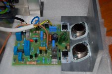
Unfortunately I haven't finished my Quad yet cause I didn't have enough free time. Hopefully tomorrow I will do a first burn-in test with one of the boards.
I ordered the boards from a Romanian pcb manufacturing company and they cost me ~32euros for 2 boards (plus the shipping another 13 😡 ...). Probably you can find a company closer to you.
You can see an image of the boards in the attachment.
Regards,
Zsolt
Attachments
Well I thought I had a good idea. I have a bunch of Toshiba sd424's, and a 60v per rail PS. (50v stock Quad 405)
So I bought these Quad 405 boards figuring that it would be easy to fill them. I can't find the transistors anywhere. I figured with a PS, heat sink, case, and outputs I would have a fun little project. No fun so far🙁
http://cgi.ebay.com/ws/eBayISAPI.dll?ViewItem&rd=1&item=120195098578&ssPageName=STRK:MEWN:IT&ih=002
Re transistors. Don't despair. Common equivalents will work fine.
I will try to dig out my old files to see what I used. Anyway there is plenty of info on the web.
I will try to dig out my old files to see what I used. Anyway there is plenty of info on the web.
Why not use the MJ15003? Just wished someone made PCBs based on the Keith Snook circuitry. Zsolt's PCBs are looking fine but I miss the clamp circuitry.
Roger
Roger
@ben62670
You can use a wide variety of transistor types for this amplifier.
Google for Bernd Ludwig's Quad 405 updates. On the end of the article you can find some replacement options.
I highly recommend to read Keith Snook's page QUAD 405 Modification , and doing the input and C8 modifications he suggests.
I used the following transistors:
Tr1 - 2SA970
Tr2 - 2SC2240
Tr3 - MPSA92
Tr4 - ZTX753
Tr7,8 - MJE15031
Tr9,10 - MJ15003
Has anyone checked out this blog?
http://quadrevisionspot.blogspot.com/
There's loads of info about transistor replacements etc if you search. it really helped me when i rebuilt my 405 to the dcd version.
Does changing the inductors make much difference on the 405? I still have the originals in, they're pretty much the only original components.
Cheers,
Lee.
vzs said:@ben62670
You can use a wide variety of transistor types for this amplifier.
Google for Bernd Ludwig's Quad 405 updates. On the end of the article you can find some replacement options.
I highly recommend to read Keith Snook's page QUAD 405 Modification , and doing the input and C8 modifications he suggests.
I used the following transistors:
Tr1 - 2SA970
Tr2 - 2SC2240
Tr3 - MPSA92
Tr4 - ZTX753
Tr7,8 - MJE15031
Tr9,10 - MJ15003
Marked 🙂
I have 500 toshiba SD424's and 554 So I will be using them for out puts. Thanks so much for the transistor list. I could not find nearly any of those old transistors

Thanks Again so much.
Ben
Edit
I am ordering some OP97FPZ OpAmps for anothe project would these work well with this project?
Thanks
Ben
Hope you guys don't mind me coming in on this thread, but I think this may help
The original Quad transistor is in Italics.
TR1: BC214C - BC559C BC415C BC560C
TR2: ZTX304 - BCX32 BC682 MPSA06 2N5551 - BC546B
TR3/TR4: ZTX504 - BC556B – ZTX753
TR5/TR6: BC214C - BC154 - BC560
TR7/TR8: 40872- 2SA740 2N6134 TIP42C BDX78 - BD242C
TR9/TR10: 17556- 2SD424 2SD676 3N3773 - MJ15003
The transistors I used are the last ones in the list
Lee.
I have ordered everything. The only problem is BC560, and BC560c came up as the same part.... BC560CTACT.
I hope this is fine.
I hope this is fine.
I would have used what Keith Snook recommended but I couldn't find 2SA1085E, neither 2SC2547E.
I think the difference between BC560 and BC560C is their different DC current gain and small-signal current gain (hFE and hfe).
The A types have the smallest and the C types have the highest current gains. There is no need for high gains here, but probably you would be fine with the BC560C.
As RogerGustavsson said, I would use what Keith Snook has recommended or the parts that I or Thomo has recommended are fine also.
Tell us whether you have managed to make it.
If you managed to make it sing, than you should try Keith Snook's mods, at least for one side Quad 405 modification (then you will do the other side too 😉 )
I am ordering some OP97FPZ OpAmps for anothe project would these work well with this project?
I have never used OP97FPZ, so I don't know.
The OpAmp is very important to be of high quality. I used OPA627 but LME49710 would be also a very good choice.
You should also take care to use 1% tolerance components in the bridge, C8 - silvered mica, R38, R20, R21 metal film resistors (you should use metal film resistors elsewhere too), and try to find a good inductor for L2 (5-10% if possible).
For C1 and C4 I used polypropylene capacitors. You can find pretty good ones from Epcos or Wima.
- Status
- Not open for further replies.
- Home
- Amplifiers
- Solid State
- Quad 405 DCD mod3 - PCB