Guys,
If you need someone in the UK to do a group buy of components, then I'll volunteer! It's fairly easy to get anything needed here, but price is another matter. (I use Farnell a lot because they have most things, are extremely fast, and have a good web site. But cheap they aren't.)
If you need someone in the UK to do a group buy of components, then I'll volunteer! It's fairly easy to get anything needed here, but price is another matter. (I use Farnell a lot because they have most things, are extremely fast, and have a good web site. But cheap they aren't.)
RogerGustavsson said:AD845 are very sensitive devives that will easily oscillate. 0.1µF capacitors (or larger values) on the supply lines to ground is a must for most high speed devices.
Roger
Hi Roger!
I placed 0.1uF MKS caps from Vcc+ and Vcc- to signal ground. For routing reasons I used OP pin 3 (IN+) as ground, since it goes directly to ground. I hope that isn't a no-no for some reason?
Hälsningar
I have a general question regarding the current dumping design:
(Sorry if this has been asked before!)
How will the amp behave if the current dumper is unable to dump enough current to bring the output voltage into range for the class A stage to operate properly?
I assume the class A stage will swing as much as it can, delivering as much current as it can?
If so, would this event be worse in a current dump design than in other designs? (I still have just a vague idea about the exact workings of the bridge, etc.)
Regards
PCB design files
Hello folks,
Would one of you who has gone to all the trouble of laying out the PCBs (VZS or Guillaume) we willing to share the design files to that I can be a little lazy and not have to re-do the layout from scratch? PDF format doesn't cut it with PCB fabrication outfits.
Personally I use EagleCAD, but if you have worked the design in a popular package like Altium, PowerPCB, etc, I can probably find a way to deal with it. I would be so very grateful for the saved effort!
Merci,
Natan
Hello,
I've attached the Altium project files.
Feel free to modify it as you wish but please post the modifications here also! Someone might found it useful.
As I suggested back at post #23 some minor modifications could be done to improve the pcb.
I also bypassed Tr3 and removed R18, to keep the class A stage as in the latest Quad 405-2 models. This bypassing can be done on the pcb as well, I did it there.
I removed Tr3 and R18 from the Altium schematics but not from the PCB, feel free to remove there also.
I've soldered further decoupling capacitors, Panasonic FC 1000uF/63V for +/- power and 100uF/63V for the operational on the back of the pcb, but you can leave them out. These are too big to be fitted on the component side, so don't bother to make room for them. Maybe if you move the protection fuses to the PSU side you could make more room.
As Bernd Ludwig suggests in his modification document at 1c you could improve the OPA's power supply by feeding it via some medium power transistors: BD139 and BD140
Regards
Attachments
Hello Roger - Tibi - All
Just a few points I noted while re-reading this thread
The 2SA 2SC transistors I use are high (but restricted range) hfe - high voltage so in the 405 R17 and R23 and associated caps can be shorted/removed - and very low noise which with R12 source makes Tr2 very quiet - Beware the transistor voltage rating if applying all my mods
My mods are not severe or complicated and the excellent thing about modifying the 405 is that you can do it in stages to see what difference each step makes - Input non-inverting and 2SC2547E for Tr2 greatly improves S/N - Current source Tr1a/b (Tibi thanks) improves distortion - C8 re-positioned . . . You can choice where to start and how far to go which I think makes the 405 a perfect DIY platform
DCD Mod-3 and DCD Mod-4 are very different from the Class A and output stage but front end the same and yes Tibi you may well have made an RF oscillator - From some feedback I have been sent so have Net Audio with their Mk3 PCBs but this is easy to cure if you can test for it correctly as it may be part op-amp and part loop stability of the Class A with current source
AD845 or any op-amp requiring C to keep it calm in an audio circuit I would avoid - On more than one occasion I have been presented an amplifier or pre-amp that 'actually' did sound different when op-amps were substituted - In some cases the offset voltage/current of the 'wrong' op-amp were giving incorrect operating conditions and in others the device oscillated at HF/RF causing the output to compress
One thing that I have not seen highligted anywhere else [ correct me ] is that the op-amp in the 405 is operating "class A" - The output never crosses negative through 0V and as most op-amp distortion is around 0V or at peaks and most are not specified for asymmetric operation then why fit over priced op-amps where you are paying for speed and elaborate zero crossing distortion reduction circuitry?
If you have the screens of the input leads connected to chassis at the input connector [ like you should ] and you have more than a few mV of offset voltage at the speakers then consider that something is wrong and that the something may be your choice of expensive op-amp
Regards Keith
Hello Keith,
You are partially right. 🙂
The op-amp will be forced to work into class A only al low input signals and this is only valid for your input stage where the gain is lower (gain=7,6).
In original QUAD405 (gain=15) opamp will run most of the time in asimetric classB.
The asimetric output is due Vbe Tr2.
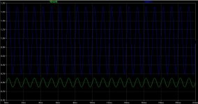
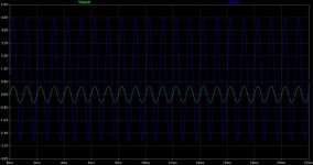
Attached you have two simulations with 0.1Vpp input and 0.5Vpp.
Regards,
Tibi
You are partially right. 🙂
The op-amp will be forced to work into class A only al low input signals and this is only valid for your input stage where the gain is lower (gain=7,6).
In original QUAD405 (gain=15) opamp will run most of the time in asimetric classB.
The asimetric output is due Vbe Tr2.
Attached you have two simulations with 0.1Vpp input and 0.5Vpp.
Regards,
Tibi
Attachments
Tibi
I guess in the world of voltage only analysis I am only about 9% right when considering Tr2 Vbe plus the voltage across R16 [ 180Ω ] compared to the required negative voltage swing at Tr2 base for full output
But what amounts to crossover distortion in say an op-amp output ? With no load on the output or the output current never changing direction is the crossover measurable ?
From the superficial viewpoint of simply accepting that the base of Tr2 cannot go negative or even close to negative the op-amp output would appear to be "class A" and this is where I started
Extend the analysis back into the op-amp output circuit and accept that it will have 2 output "devices" one TOP between +supply and out and one BOT between -supply and out
—{ The owner of the Pub looked up at his new sign and said to the signwriter - You have not put enough space between FOX and and and and and HOUNDS }—
For the base Tr2 to swing -11V as required for full output it must be pulled down by the output of the power amp via R20//R21 — The current into the base of Tr2 is always in the same direction and is only supplied by TOP device of whatever op-amp is fitted and no matter what other currents BOT may be swinging it does not contribute to the base current of Tr2
So what Class of op-amp output is this ?
Does having a high standing current flowing Through TOP and BOT make the op-amp "sound" better ?
Is it worth modifying a 405 to accept high supply current op-amps ?
Is the 405 design with "fast" op-amps more susceptible to instability but only on negative going cycles ?
Should the op-amp go altogether ?
Equal points will be awarded for answering each question - Start writing now
Keith,
You are right. My analysis was superficial and indeed opamp will run only in class A.
Regards,
Tibi
You are right. My analysis was superficial and indeed opamp will run only in class A.
Regards,
Tibi
Does having a high standing current flowing Through TOP and BOT make the op-amp "sound" better ?
Well, depends. This is related to opamp and how much power can dissipate.
Anyhow Tr2 base current is very low and for sure a great variety of opamps will be able to handle this.
Is it worth modifying a 405 to accept high supply current op-amps ?
Yes, because I'm confident that a good opamp is still necessary even his output is running class A.
Is the 405 design with "fast" op-amps more susceptible to instability but only on negative going cycles ?
Usually fast, means opamp not internally compensated. Anyhow the moded input gain is over 5 which is the "threshold" stability for many high speed opams.
But, even the gain is over "threshold" a fast opams with poor supply will easily oscillate.
A well decoupled opamp and a very good supply is still necessary.
Should the op-amp go altogether ?
I don't want to start an opamp versus discrete debate, but there are very good opams with performance which is very hard to achieve with discrete components.
Regards,
Tibi
Dear Sirs
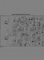
I am seeking the Quad 405 M12368 ISS10 PCB Drawing (Original).
Does any one have it?
I am ready to buy a copy .
Best Regards
Jose Paulo Beltrao Serra Pinto
I am seeking the Quad 405 M12368 ISS10 PCB Drawing (Original).
Does any one have it?
I am ready to buy a copy .
Best Regards
Jose Paulo Beltrao Serra Pinto
eliminate L3 and L1
Hi,my question is about L1 and L3/6,8 uH/.Why do you eliminate this elements and use L4,R37 in Tr8 emiter circuit?
Hi,my question is about L1 and L3/6,8 uH/.Why do you eliminate this elements and use L4,R37 in Tr8 emiter circuit?
Hi,
Sorry to revive an old thread, but I'm wanting to rebuild an already modified 405-2 and find that the original PCB is falling apart when I desolder. So I have to either order a new PCB from Quad or, hopefully, find one that is closer to Keith's DCD mod 4, that I'm hoping to base my rebuild on.
I don't have Altium (Linux user) so can't open the files from VZS's earlier post, but wonder if anyone has a PCB layout that I could send to a manufacturer, or, even better, has one unused board that they could sell to me.
Amp will be part of a 3 channel design with completely independent PSU's but the channels will share a cabinet. Any advice regarding stability, DC protection and ground topology would be appreciated.
Latest DCD Mod-4 PCBs
I am also interested in buying Mod-4 PCBs. Please send private message or email.Hi,
Sorry to revive an old thread, but I'm wanting to rebuild an already modified 405-2 and find that the original PCB is falling apart when I desolder. So I have to either order a new PCB from Quad or, hopefully, find one that is closer to Keith's DCD mod 4, that I'm hoping to base my rebuild on.
I don't have Altium (Linux user) so can't open the files from VZS's earlier post, but wonder if anyone has a PCB layout that I could send to a manufacturer, or, even better, has one unused board that they could sell to me.
Amp will be part of a 3 channel design with completely independent PSU's but the channels will share a cabinet. Any advice regarding stability, DC protection and ground topology would be appreciated.
Hi Learnincurve, spurlte,
I cannot help with latest DCD Mod-4 pcbs. This Quad is slightly different from the classic Quad outputs being based on complimentary bipolar or mosfet output stage.
Tibi (tvicol) seams to be tweaked the latest drop of juice out of this configuration with his Quasar named amplifier.
I happen to have two boards from the very first group buy, ver. 11, which I'm willing to sell: the red boards from the link. Contact me on PM if you are interested. It can be easily modified to the newer ver.12 : Quasar
Regards,
Zsolt
Last edited:
Hi Zsolt,
Thanks for the links and the offer.
The Quasar looks great, but it's not a quad 405. What I want to do is tweak the original design as far as possible on something approaching original boards. Having said that. If I had the space for it and wanted to build the ultimate current dumper, I might go for the Quasar 🙂
Cheers!
- Status
- Not open for further replies.
- Home
- Amplifiers
- Solid State
- Quad 405 DCD mod3 - PCB