pay attention to what batteryman said (and me)
the input 0v is connected thru a 10ohm resistor to the center screw on the h\s which is connected thru the case to 0v,
this is missing in yours
the input 0v is connected thru a 10ohm resistor to the center screw on the h\s which is connected thru the case to 0v,
this is missing in yours
Last edited:
pay attention to what batteryman said (and me)
the input 0v is connected thru a 10ohm resistor to the center screw on the h\s which is connected thru the case to 0v,
this is missing in yours
Hmm, it might be the case. Well, just measure resistance (or continuity test) between the LM301 pin 3 and the ground (PGND). If it's reading 10 ohms, then the issue is the improper grounding for sure.
Last edited:
OK.Yes pin 4= 13.93 minus
You also measure around +12 volts on the opamp output. That will turn on the first NPN which is Q2 in my simulation. In turn that will turn on the whole of the upper half of the output stage putting a high positive voltage on the speaker output.
You need to find why that high output at the speaker is not (via the feedback) swinging the opamp output negative.
Measure the voltage on pin 2 of the opamp. It should (with your fault) be a positive voltage via R4 and R5. That should give a negative output on the opamp which is not happening. See what voltage is on pin 2.
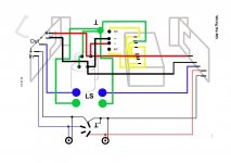
I have connected all the gnds as per the attached Dada diagram, all gnd meet at the star point which is attached to the case via a bolt which in turn also has the mains earth connected, is this set up wrong? should the star point be floating?there is a gnd connector to the middle of the pcb, has that been connected to the case or 0v ?
Attachments
Between those points the resistance is 002.7 OhmsHmm, it might be the case. Well, just measure resistance (or continuity test) between the LM301 pin 3 and the ground (PGND). If it's reading 10 ohms, then the issue is the improper grounding for sure.
measures 16.74 +OK.
You also measure around +12 volts on the opamp output. That will turn on the first NPN which is Q2 in my simulation. In turn that will turn on the whole of the upper half of the output stage putting a high positive voltage on the speaker output.
You need to find why that high output at the speaker is not (via the feedback) swinging the opamp output negative.
Measure the voltage on pin 2 of the opamp. It should (with your fault) be a positive voltage via R4 and R5. That should give a negative output on the opamp which is not happening. See what voltage is on pin 2.
measures 16.74 +
That's a big clue. Once the inverting input (pin2) goes more positive than pin 3 the opamp output should swing hard negative, all the way to the minus opamp supply.
I'm going to say either the opamp is faulty, its fake, there is a break in connection between the board and the IC socket and the IC, or (unlikely) its oscillating like crazy and giving misleading readings.
Check the connectivity from board to IC pins first. Any common single opamp should work as a test.
on this board the center h/s screw +PGND point on the board and pin 3 on the opamp are all connected (continuity test) should I test another way?pay attention to what batteryman said (and me)
the input 0v is connected thru a 10ohm resistor to the center screw on the h\s which is connected thru the case to 0v,
this is missing in yours
all those are connected together but they should go to the 0v at the capacitors thru the 2.7 ohm (in this case) resistor,
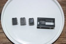
Yes! took a few tries and some serious rooting around in the parts box but the fourth one worked (JRC) so no smoking hot r30/31 and less than a milivolt at the speaker out. I have some TL071CP if I want to use those I take it some component changes are required?That's a big clue. Once the inverting input (pin2) goes more positive than pin 3 the opamp output should swing hard negative, all the way to the minus opamp supply.
I'm going to say either the opamp is faulty, its fake, there is a break in connection between the board and the IC socket and the IC, or (unlikely) its oscillating like crazy and giving misleading readings.
Check the connectivity from board to IC pins first. Any common single opamp should work as a test.
Attachments
Yes 👍
The OPA604 could be an excellent choice I would have thought as long as you are sure they are genuine. No modifications should be needed apart from making sure you remove any cap fitted between pins 1 and 8. The LM301 needed that. Not sure the 5534 would need anything like that because it is being used at high gain here and in any case it would be pins 8 and 5 for the cap on the 5534. We'll say no cap.
If you are saying only the 5534 worked out of all those then you have to question whether the others are genuine/fake or look at the other possibility which is that ALL are good and the amp has a problem with stability and the 5534 is just one that happens to work. You would need to use a scope to check on that.
No scope I,m afraid but your point re Genuine/fake is something I will careful about when buying parts. Many thanks to you and all who contributed to resolving this problem.Yes 👍
The OPA604 could be an excellent choice I would have thought as long as you are sure they are genuine. No modifications should be needed apart from making sure you remove any cap fitted between pins 1 and 8. The LM301 needed that. Not sure the 5534 would need anything like that because it is being used at high gain here and in any case it would be pins 8 and 5 for the cap on the 5534. We'll say no cap.
If you are saying only the 5534 worked out of all those then you have to question whether the others are genuine/fake or look at the other possibility which is that ALL are good and the amp has a problem with stability and the 5534 is just one that happens to work. You would need to use a scope to check on that.
Well good luck with it 🙂 The OPA604 is definitely one to be wary of (fakes) and I'm not even sure its available now in a DIP8 package. The TL071 is a great all rounder.
Ok great, but still, if DMM is reading 2,7 ohms between U1 pin 3 and PGND then it means AGND is still floating. This must be sorted out, at least for the sake of science.

Last edited:
At face value yes, it needs sorting. I would need a board in front of me to see how its configured though.
Anything else you would like me to check?Ok great, but still, if DMM is reading 2,7 ohms between U1 pin 3 and PGND then it means AGND is still floating. This must be sorted out, at least for the sake of science. View attachment 1118850
the pics I posted in #8 are the best I haveAt face value yes, it needs sorting. I would need a board in front of me to see how its configured though.
Working off pictures can be very difficult tbh 🙂 You need to be able to spin it around and measure.
If you take the input ground as a reference point then all points on the original circuit that are connected to ground should of course read zero ohms back to that reference point.
If you take the input ground as a reference point then all points on the original circuit that are connected to ground should of course read zero ohms back to that reference point.
It is correct... its a very clever circuit that isn't easy to just figure out at first glance. There were many updates to it and the one I posted is one of the first original variations.
It is not correct. D6 is in the wrong place, for a start.
- Home
- Amplifiers
- Solid State
- QUAD 405 clone high DC on output