0V is OK for the top of C306, which is connected directly to pin 1, but the other one should be 5.4V, so something isn't drawing current. What do you measure at the top the central 100uF capacitor (C313)? Should be 10.4V. But as a matter of course I would change all 9 caps on this board, especially if they are still the original plastic ones. Also R300 and any other one that measures wrong.

Both should be similar. Maybe remeasure and make sure of a good connection. Sometimes lacquer or flux can insulate a component lead. 6.7 volts sounds a viable voltage given the 12 volt supply.
If by chance it is still at zero then that would be strange because if it were a one off definite fault then the other channel should still work. Two faults suggest something other than a natural failure somewhere.
Ideally you would use a scope now to trace the signal through the phono stage.
If by chance it is still at zero then that would be strange because if it were a one off definite fault then the other channel should still work. Two faults suggest something other than a natural failure somewhere.
Ideally you would use a scope now to trace the signal through the phono stage.
Not at the measurement points you suggested. The top of C306 is grounded via pin 1 and R112. The top of C305 isn't. The voltage marked on the schematic at that point is 5.4V, not 6.7V,, and the voltage on this board is not 12V but ~10.4V due to R300.Both should be similar.
Last edited:
Fair enough on R300 🙂 although the board is supplied by 12 volts according to the diagram.
6.7V doesn't sound to far off the voltage in the manual and its in the right ball park. The 12v is from a simple Zener shunt supply by the looks of its so could be a bit higher or lower than marked.
So we have to be sure on the two caps and be sure both channels are biased correctly. Just measure on the other end of the cap then to confirm the same voltage as the other cap. The service data manual I'm working from hasn't got PCB layouts in it unfortunately.
thanks - im working on closing the spring connects on all boards as they are very slack when fitted - wobbling around - ill do a remeter after
OK 🙂
These things are never easy without having one in front of you. You could also look at some continuity checks. You know the line inputs work. The phono stage ultimately feeds into the what becomes the line stage.
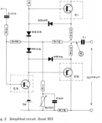
The switches are not easy to draw a path through but I think you should expect to find continuity between these points when you select phono.
The two circled points at the right are the left and right inputs to the line stages.
The two circled points at the left appear to be the outputs of the phono stage.
Either of the the points at the left should have continuity to one of the points at the right when you select phono.

These things are never easy without having one in front of you. You could also look at some continuity checks. You know the line inputs work. The phono stage ultimately feeds into the what becomes the line stage.
The switches are not easy to draw a path through but I think you should expect to find continuity between these points when you select phono.
The two circled points at the right are the left and right inputs to the line stages.
The two circled points at the left appear to be the outputs of the phono stage.
Either of the the points at the left should have continuity to one of the points at the right when you select phono.
1. It sounds like you have one dead channel drawing no current, or less current, so either one or both of the transistors or the resistors that load them.
2. If you have a very early 33 it is possible that I am wrong above about the DIN socket. I have seen them where the input was on pins 1 and 3 instead of 5 and 3. If you have one of these, change it to 5 and 3, just by changing the lead to pin 1 to go to pin 5, and keep using standard cables. This is better than going to non-standard cables and confusing yourself and everyone else forever. Note that the pins are numbered 1-4-2-5-3 for historical reasons: check the 33 schematic.
If that happens to be the case it affects the R channel. If the non-working channel was L, this would explain the total silence.
Hi members, 21 years ago I repaired 2 QUAD 33 belonging to my brother & a friend of he. Problems was no sound on different input and other function with other push-button switches. After some few check on signal path, it pop up that the problem was the entire push-button switches. Remember that your QUAD 33 is approx. 40 years old...! So I opened up 1 at a time each QUAD 33, unsoldered 1 at a time each pushbutton switch, took time to open each switch and found that inside the contacts there was black deposit that causes contact resistance and even total open circuit.... after cleaning everything on each switch and reclosing switch enclosures, I brought them like brand new but let say refurbished. I know it's a long job but it worth it. To make sure that it's that, you could make a selection of input and short with a wire in parallel with selected input at the switches and track your signal. And the proposition of changing every polarized capacitors is a very good idea because after all those years the electrolyth liquid inside of these parts may have dried and will lead to shortened frequency response and even open circuit, as well as bad filtering on power supply. It's a nice vintage equipment that deserve a try!
OK. Since this thread is about VINTAGE audio, let's write VINTAGE problems. Capacitors issue is a vintage problem in old audio. In 1989 on a summer job at Radio-Canada in an audio repair department, QUAD 303 amplifier was used from wall to wall. In the VINTAGE time, many constructors were using single supply on their audio. Meaning for the QUAD 303 here that speaker had to be coupled threw a 6800uF capacitor which with time will lead to a limited frequency response cutting from bass to mid and eventually ending open circuit with no sound. I repaired approx. 22 amplifier that summer!
22 years ago, I had a VINTAGE MA6200 of McIntosh with intermittent sound cutting. Here the problem was the relay socket that held the speaker delay. Even changing the relay socket would not fix the problem.... so I decided to solder the wires directly to the relay which fix the problem. Few years after input selector began to cut sound randomly. After looking for parts at McIntosh, parts were already obsolete since many 10th of years!
With the QUAD 33 discussed here, those mechanical parts are already obsolete. Only you can fix this!
does the line ins sounding amazing mean that power supply filter caps can be discounted from the thin sound- also on ebay Ferndale replacement boards - any opinions?
You will only feel supply weakness with large output signal, since voltage will crush because capacitors fails to keep maximum charge for large signal drive. It will sound harsch. Meaning that ripples out of diode rectifier supply will be noticeable and modulate audio signal. Ripples in ripples out at large signal. With doubt and since it's cheap, I would change them and you forget about them for the next 10 years.... and any refreshning of vintage audio parts is always good! After looking at schematic I see 3 easy to find capacitors!!
If it's capacitor, 22uF / 16 volts. In the +12V power supply I see one 680uF and two 1000uF. And the supply feeding the output connetor I see one 47uF and one 100uF. But this second supply might serve with QUAD external amplifier I believe since it's route thru output connector SK6!
Last edited:
It just pop up now... when you wrote about thin sound, lack of bass, this is the sign of coupling capacitors dying slowly and name C406 with value of 2.2uF coupling with output also C200 & C201 with value of 33uF coupling at the input. Also the decoupling capacitor name C406 with value of 50uF that set whole preamp gain at the transistors. In fact ALL electrolitic capacitors should be changed. It'll cost you just a few pounds(UK). These changes will restore frequency response, dynamic and good quality supply.
And I must correct in my previous long post, the capacitors that was changed in my 22 amp repaired wasn't QUAD 33 but QUAD 405 100W monobloc!
Here again capacitors failed over time...
And I must correct in my previous long post, the capacitors that was changed in my 22 amp repaired wasn't QUAD 33 but QUAD 405 100W monobloc!
Here again capacitors failed over time...
I joined pictures of the 303 and look at C1. Because my repaired has been done like 34 years ago I forgot model... now yes this thread in on QUAD 33 and the 33 uF that I talk about is at the input of the QUAD 33. Also the 2.2 uF are at the output of the QUAD 33, Now let's say that generally any preamp or amp that has a single polarity power supply MUST be coupled via capacitors because the inside circuit in mainly held at half the power supply, in order to give maximum amplitude at output and the QUAD 33 is no exception. The swing will be given from 0V to +12V here inside the QUAD 33 but at the output connector it will be seen like +/- 6V. Now try to open schematic of the QUAD 33 and take a good look. And yes QUAD 33 only! In the 1970-80 design with single polarity power supply was very popular in audio!
Attachments

Last edited:
My post was to help jkojic pushing him to restore his QUAD 33 line level preamplifier or anyone else. And keep in mind that line level discrete parts preamp and power amp are very close design...! Their differences are power supply voltage and size of output stage. The QUAD 33 has a single transistor TR201 hook as a Class A amplifier and buffering is achieved by TR402 as a emitter follower to boost current output. I can understand why people having QUAD 33 wants to keep it. It's a nice piece of equipment.
- Home
- Source & Line
- Analogue Source
- QUAD 33 phono cards