When you call it an 'earth lift' it seems like you are mixing up earthing and grounding. There are devices to break an earth loop, and a ground lift for elevating ground above earth potential.
Can you link to the documentation of the tweak?
Can you link to the documentation of the tweak?
Hi juancho,
I read the thread again from the start. From what has been posted, your plate voltage is only a little high, the grid voltage is 345 mV without the outputs. You have +40 VDC on pin 5 (grids) with the output tubes installed. Is this correct?
Therefore, this must be a fault with oscillation since your DC connections with the feedback broken (outputs removed). Strong oscillation to put it mildly. So test #1, disconnect R11 (470R) to break feedback. That was suggested earlier. If you still see a strong positive voltage on the grid, you must have a defective output tube.
I also noticed that you were told these amplifiers were working properly before you rebuilt them. Did you actually test them in their "as received" condition?
YesHi juancho,
I read the thread again from the start. From what has been posted, your plate voltage is only a little high, the grid voltage is 345 mV without the outputs. You have +40 VDC on pin 5 (grids) with the output tubes installed. Is this correct?
Tried and reportedTherefore, this must be a fault with oscillation since your DC connections with the feedback broken (outputs removed). Strong oscillation to put it mildly. So test #1, disconnect R11 (470R) to break feedback. That was suggested earlier. If you still see a strong positive voltage on the grid, you must have a defective output tube.
No but no reason to doubt the ownerI also noticed that you were told these amplifiers were working properly before you rebuilt them. Did you actually test them in their "as received" condition?
Coming in late on this thread but here are some items for the curious, lurkers & others.
A very thorough item by Patrick Turner. And comments by Morgan Jones.
The cathode resister I found was in a limited space, not able to dissipate heat.
Should be rated at least 5W.. Heat sinking resister to the chassis if possible would be a useful fix.
A very thorough item by Patrick Turner. And comments by Morgan Jones.
The cathode resister I found was in a limited space, not able to dissipate heat.
Should be rated at least 5W.. Heat sinking resister to the chassis if possible would be a useful fix.
Attachments

Hi juancho,
What I would say at this point is to reexamine everything. Start completely fresh as if someone else did your work and brought it to you for repair. The answer is there. Do it later when you get back into it.
Make each test and measurement, record only what you have proved or measured. Nothing else, no conclusions, nothing you were told. Test the output tubes as they may be damaged at this point. Check each resistor value you installed. Your answer will be in there somewhere.
Do you have an oscilloscope and variac?
Good technicians only get stuck in two situations. There is a simple fault they overlooked, or they made an assumption which they accepted as a fact.
Please put the response here. I am trying to get pertinent information close together. I don't have time to search for your earlier answer. Help us help you.Tried and reported
There is every reason in the world to doubt the information you were given. I've serviced for nearly 50 years professionally. You always confirm everything and assume nothing. I have been given mistaken information from clients I trust more times than I can count. Everyone makes assumptions and hopes for the best. Sometimes things happen to equipment they forgot about or were not aware of.No but no reason to doubt the owner
What I would say at this point is to reexamine everything. Start completely fresh as if someone else did your work and brought it to you for repair. The answer is there. Do it later when you get back into it.
Make each test and measurement, record only what you have proved or measured. Nothing else, no conclusions, nothing you were told. Test the output tubes as they may be damaged at this point. Check each resistor value you installed. Your answer will be in there somewhere.
Do you have an oscilloscope and variac?
Good technicians only get stuck in two situations. There is a simple fault they overlooked, or they made an assumption which they accepted as a fact.
OK so you assume they were working when you got them. Before you did any mods could you see any work that had already taken place.
I serviced many II without any issue , it is easy if the OT is good!
In this case I think that if the output stage wiil be electrically separated from input maybe will be a good idea
In this case I think that if the output stage wiil be electrically separated from input maybe will be a good idea
Hi juancho,
In no way am I insulting you or ignoring any experience you have had. I ran a shop for 16 years and part of my work was to go over every tech that was stuck on a repair. This is what always lead to an answer. I am trying to be helpful. If it makes you feel any better, when I get stuck, I follow this procedure myself on my work. It's harder to do alone, but even talking to another tech can show you an answer or path.
Also, can you forget everything you "know" about this repair and start fresh?Do you have an oscilloscope and variac?
In no way am I insulting you or ignoring any experience you have had. I ran a shop for 16 years and part of my work was to go over every tech that was stuck on a repair. This is what always lead to an answer. I am trying to be helpful. If it makes you feel any better, when I get stuck, I follow this procedure myself on my work. It's harder to do alone, but even talking to another tech can show you an answer or path.
Joining the group that read the thread again from beginning and found there is nothing clear about the situation. It's not even clear if the amps even worked before the mods, then the mods were done at the same time on both monoblocks making it more diff to understand. IMO any discusson of earth lifing is meaningless to the problem.
Since there seem to be more QII in hand, measurements can be done and conditions mirrored to figure out the problem.
Since there seem to be more QII in hand, measurements can be done and conditions mirrored to figure out the problem.
Last edited:
When a power tube quickly goes into full conduction and the cathode resistor goes into heat...mostly. g1. is not in normal mode.
What Hooman says is what I suspected from post #2. There's some issue with the resistor(s) grounding grid 1 somewhere.
If the OP would finally disconnect the power stage from the driver (removing coupling capacitors from grids) would be cleaner the situation.
I wrote same words some post beforeIf the OP would finally disconnect the power stage from the driver (removing coupling capacitors from grids) would be cleaner the situation.
Both monoblocks have the same answer. Perhaps a replaced part is defective in both.Hi juancho,
Please put the response here. I am trying to get pertinent information close together. I don't have time to search for your earlier answer. Help us help you.
There is every reason in the world to doubt the information you were given. I've serviced for nearly 50 years professionally. You always confirm everything and assume nothing. I have been given mistaken information from clients I trust more times than I can count. Everyone makes assumptions and hopes for the best. Sometimes things happen to equipment they forgot about or were not aware of.
What I would say at this point is to reexamine everything. Start completely fresh as if someone else did your work and brought it to you for repair. The answer is there. Do it later when you get back into it.
Make each test and measurement, record only what you have proved or measured. Nothing else, no conclusions, nothing you were told. Test the output tubes as they may be damaged at this point. Check each resistor value you installed. Your answer will be in there somewhere.
Do you have an oscilloscope and variac?
Good technicians only get stuck in two situations. There is a simple fault they overlooked, or they made an assumption which they accepted as a fact.
Hi hooman,
Both were modified at the same time. If an error was made or incorrect part was used, I would expect both to be the same. I've modified pairs enough times, you use one as the reference for the other.
I don't think anyone will get anywhere with guessing now. Really it comes down to confirming things and listing facts. That is something only juancho can do in his own time. I'm just waiting for his findings.
Juanco
Some remarks:
The KT66 screens are connected directly to the B+....I never like doing testing without a resistor in series to the B+ as it´s so easy to destroy the output tubes.
The Quads like many amps of the era use lacing cord and wiring harnesses.....Have you disconnected and resoldered the "wrong one" on the output tube sockets ? IMO pins 3,4,5 on octal sockets is the worst possible proximity configuration !
Many components of the 1960´s (as you typ. mentioend micas), they may look like resistors, and resistors look lke caps. Inductors also. That was then commonplace.
BenchBaron
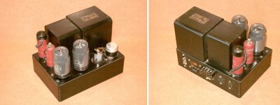
I am a layman who owns a pair of Quad II amps so he reads most of information and posts about them in an effort to learn and understand.
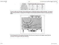
The 22pf cap mod could be this.

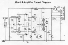
The complete discussion is here.
https://keith-snook.info/quad-ii-valve-power-amplifier.html
About "ground lift" I have no idea but I do know that an alternative "safety earth" connection is required if the original Quad 22 pre is not used to drive the amps. This is necessary as it is the pre that provides the " safety earth" . As I do not use the pre , I use a three core wire with a three pin plug on the wall socket side , a two pin female to on the amp side and then tie the earth wire to the nearest chassis screw.
Regards,
The 22pf cap mod could be this.
The complete discussion is here.
https://keith-snook.info/quad-ii-valve-power-amplifier.html
About "ground lift" I have no idea but I do know that an alternative "safety earth" connection is required if the original Quad 22 pre is not used to drive the amps. This is necessary as it is the pre that provides the " safety earth" . As I do not use the pre , I use a three core wire with a three pin plug on the wall socket side , a two pin female to on the amp side and then tie the earth wire to the nearest chassis screw.
Regards,
Thanks for all the replies. Now back from Easter and back to the amp. I removed the earth lift circuit and ran it up on the Variac. Same result.
Swapped out the valves for some known good but old ones and all works perfectly. Restored the earth lift circuit and all works perfectly. I'm only surprised that both amps acted identically! But glad it had a simple solution!
Swapped out the valves for some known good but old ones and all works perfectly. Restored the earth lift circuit and all works perfectly. I'm only surprised that both amps acted identically! But glad it had a simple solution!
- Home
- Amplifiers
- Tubes / Valves
- QUAD 2 Problems