i have a couple of qsc's and some of their clones (american audio for one) here in the shop for repair...... the "backwards" way that they produce output is interesting. the output devices are grounded, with the emitters "driving" the rails, and the "0V" line of the power supply floats, and is the speaker output....... other than the fact that the speaker is capacitively coupled without an additional capacitor (it's coupled through the power supply caps), are there any other advantages to this design? also, the american audio clone i have in the shop here is also a class G design in addition to the qsc-like "driven rail" setup
The main advantage to Pat Quilter's grounded-collector design is that the cases of the output transistors are at ground. This allows them to be installed on the heat sink with no insulators. Not only is this cheaper to build, it allows better heat transfer, and it's safer as well. It just takes a little while to bend your head around. 
This design is actually DC coupled. The power supply caps are not part of the signal path.
This design is actually DC coupled. The power supply caps are not part of the signal path.
Yes, do you have a (simplified) schematic of the amplifier or its concept? I too am interested in this "backwards" topology. I have seen the schematic on QSC's website, but it is VERY hard to follow because of all the parts.
BTW, the schematic that I saw is here (QSC has several models that use this topology, this is the schematic of just one of the models):
www.qscaudio.com/support/library/schems/Discontinued/EX Series/EX4000.pdf
BTW, the schematic that I saw is here (QSC has several models that use this topology, this is the schematic of just one of the models):
www.qscaudio.com/support/library/schems/Discontinued/EX Series/EX4000.pdf
you can find further reasoning on the advantages in Cherry's EW/WW paper “Ironing Out Distortion” part 2 “common emitter output stages” and the JAES references
Mikeks put scans up for a while, likely he would respond to individual requests as being covered by "fair use" rules
http://www.diyaudio.com/forums/member.php?s=&action=getinfo&userid=15776
basically Cherry's claim is that gain in the output stage is a good thing for distortion reduction in ealier stages, and no worse or actually the same as using the output devices devices in follower mode in terms of output impedance and stability
the low drive voltage at the bases/gates of grounded emitter/source output stages requires only low voltage input/driver devices which enable faster transitors or even op amp drive
tnx, i knew there had to be more than just one reason...... i still don't see exactly how it is dc coupled..... unless the dc coupling extends back through the rectifier and power transformer.......
shown below is a simplified output section
actually it's still an emitter follower, since it's the emitters are the driven element........ i figured that out after a while of standing on my head.......
shown below is a simplified output section
actually it's still an emitter follower, since it's the emitters are the driven element........ i figured that out after a while of standing on my head.......
Attachments

yes output Q current loops complete through the xfmr/rect - as always
your Qs are upside down
try this:
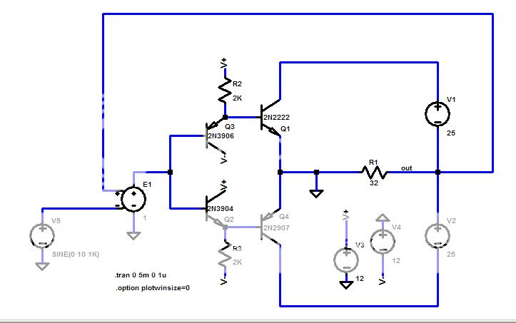
you can plot the V1 and V2 floating Vsource currents to see the usual Class AB current in each
the feedback is unitygain and the E1 source also has gain 1; the output Qs provide the large loop gain (~ 20) in CE mode that holds the distortion to -50 dB in this sim
LtSpice SwCad III file, just rename without .txt extension
your Qs are upside down
try this:
you can plot the V1 and V2 floating Vsource currents to see the usual Class AB current in each
the feedback is unitygain and the E1 source also has gain 1; the output Qs provide the large loop gain (~ 20) in CE mode that holds the distortion to -50 dB in this sim
LtSpice SwCad III file, just rename without .txt extension
Attachments
Hi,
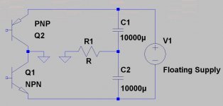
Simplified drawing of AC coupling as QSC uses on their smaller amps, no (~) need for DC protection:
Absolutely right.q's aren't upside down..... c's are grounded, emitters "drive" the rails......
Simplified drawing of AC coupling as QSC uses on their smaller amps, no (~) need for DC protection:
Attachments
logical equivalents, illogical objections...
your referenced qsc schematic follows my simplified circuit sketch
the output of the qsc amp is a pair of Sziklai/cpf compound transistors connected as per my schematic, replacing my Q1,4 with the composite (Q933 + Q903-910 = my Q1, Q934 + Q911-916 = my Q4)
http://www.dself.dsl.pipex.com/ampins/discrete/cfp.htm
for the advantages Cherry described my schematic shows the simplified output Q equivalent and is the "correct" connection for illustrating the operating principle
Your interests may differ, but there is little to be gained (pun) by driving the ps with ef - you still have to come up with the full output V swing in preceeding circuitry and the bias must be established with the full floating supply in the middle
The Sziklai/cfp is a convenient way to get lots of current gain, Ben Duncan used the same floating supply trick with grounded source MOSFETs output Qs instead of a cfp compound in one of his high slew rate amps
Grounded Source amps were built with lateral mosfets because the Centre pin of plastic package or the body of metal package is Source Terminal rather than Drain in this case.....
This type of topology is extremely simple and robust, i have made many amps using Grounded Drain Topology with IRF640/9640 Vertical Mosfets....
In these topologies only the ground reference is shifted from center tap to the usual output which makes them very easy to drive.......
Kanwar
This type of topology is extremely simple and robust, i have made many amps using Grounded Drain Topology with IRF640/9640 Vertical Mosfets....
In these topologies only the ground reference is shifted from center tap to the usual output which makes them very easy to drive.......
Kanwar
I don't see how this is different from a circlotron?
You have broken the visual appearance of the circles
with pair of ground symbols separated by white space...
You have broken the visual appearance of the circles
with pair of ground symbols separated by white space...
a circlotron is essentially a tube version of the same thing, except you have two floating supplies and the QSC uses a single (even though it's split) floating supply (actually, since the tube version came first, the QSC is a solid state version of the circlotron). the advantage of the topology for tube amps is that the output impedance is lower. the advantage of the solid state version is that it's difficult to get DC at the speaker terminals (it's not impossible, but a lot less likely)
I think you still need DC fault protection... if the output transistor shorts, one supply rail is still connected directly across the load.
Commercial versions have DC protection.
Larger QSC have the transformer center tap connected to the speaker, so they are DC coupled.
http://www.qsc.com/support/library/schems/Current/RMX Series/RMX2450.pdf
Larger QSC have the transformer center tap connected to the speaker, so they are DC coupled.
http://www.qsc.com/support/library/schems/Current/RMX Series/RMX2450.pdf
- Status
- Not open for further replies.
- Home
- Amplifiers
- Solid State
- qsc and clones.... backwards amps