I've had a desire in the back of my head for YEARS now to build a portable power amp to go with my portable speakers. Thanks to a receiver giving it up (its finals were fried by lightning and self-destructed in an impressive display of pyrotechnics, with the lightning wiping out some other parts here and there), I have a complete, functioning power supply that was used to drive a 150W/ch. stereo power amp. I 'scoped its secondaries and it's reasonably clean harmonics-wise - doesn't appear the lightning surge adversely affected it.
Plus, I found a source for TDA7293s for $2 each - and bought ten.
My gameplan is to get a suitable metal container (I'm thinking of searching for a decent condition ammo box of the large watertight steel variety as it'd be a good container for a portable power amplifier) and throw the power supply from the fried stereo, four TDA2793s in a stereo two-in-parallel configuration, and a few other misc. goodies (preamp, power meter, etc.) into it to make the portable groundpounder I was long thinking would be nice to have.
Now, I'm not overly familiar with working with this specific flavor of amp IC and thus don't know what to expect and watch out for. So I'm gonna throw out some fairly random Qs. 😀
First off, I noticed that the input and final stages of this IC have ther own power pins. Since my supply has a 50VAC center-tapped secondary coming off the transformer that is currently unattached to anything, would building up a rectification/filtering board to tap this for the input stage be better than simply driving input and final from the same supply? (I recall from an earlier board search that someone here was also playing with separating off the input stage power, but there wasn't any useful followup posted.)
Second, the heatsink I have, also cannibalized from the fried receiver, is 7" wide, 4.25" tall, and sports 18 fins, each being 1.375" tall. It weighs about 3 lbs., give or take. Assuming I can get a decent enough thermal contact for each IC, does this heatsink sound like it will have enough mass to support four TDA7293s? (Yeah, I know there's a lot of thermodynamics data that would be needed to get an accurate reading on whether/how well this 'sink will work, but all I can give are raw measurements.) If it'd be iffy, would setting up forced-air cooling (add a fan or two!) make it less iffy and more doable?
Third, for my power filtration I'm using quad 3300uF capacitors (snap-in low-ESR caps designed for power-supply filter applications) per channel, in addition to the dual 6800uF caps in the supply. Will this be adequate at least initially or would I be wise to snag a few 10,000uF monsters to add to the power filtration?
That's all I can think of right now... More as I come up with it...
O d d O n e
Go For It.....
Seperating input and output stages power supplies is usually a good thing.
Some amps use a slightly higher supply voltage for the input stages.
You would need to add seperate bridge rectifiers and caps to give seperate input stage supplies.
Heatsink - probably needs fan forced air for reliable full power operation - in my books fan cooling is required - IME keeping things as cool as possible sounds nicer.
Plenty of quite high power modern shelf systems use fan forced air on a lesser heatsink.
3" 12Vdc fans are cheap and are quiet, especially if you reduce the supply voltage to them.
Plenty of commercial hifi amps run at the most +and - 6800 uF supply capacitance, so the additional 3300 uF caps you mention should be well adequate.
Try it out.
Eric.
I agree with mrfeedback, again
TDA7293 TDA7294 are my favourites for IC power amp applications.
I asked the wellknown constructor of Parasounds legendary Phono-amp
sorry I can not remember his name (I am getting old, you know)
He said, that TDA729x was a good choice.
He had experience of some friend's construction with the IC.
And was pleased.
In this PDF is circuit suggestions and a BOARD layout.
If I could decide, I would use the supply-pin 7,8 for separate supply to the input stage.
There is never any good reason NOT TO protect the input stage from the output stage.
This common very bad pratice, comes from the commercial designs.
They would like to build anything to minimize components,
to keep PROFITS margins MAXIMIZED.
In this case SIMPLE is not GOOD at all. IT IS BAD.
A separate rectifier and smooting circuit, is the least I would like to use.
I would advocate a higher voltage to the transistors that drives
the Output Transistors. Say 5-10 Volts more, at full Output.
I assume class A operation.
TDA7293 datasheet - pdf
BTW, I plan to document the project extensively and make a how-to article on it. I wrote an article on building a rakc cabinet and it was promptly Slashdotted, so this'll be my chance to reach fo the DIY audio equivalent. 😀
Yeah, I would need to add separate rectification/filtration and that's not at all going to pose a problem.
Plus, it looks like I'll be hitting the driver section with ~#17736VDC and the preamp section with about ~#17730VDC, so there'll be a slight self-limiting effect as the preamp maxes out before the drivers start to get into their higher-distortortion output levels.
I figured I'd need at least one fan, and I'll duct the HS fins to get better thermal transfer into the moving air.
I have eight 3300s here, waiting for their time in the sun. I'll probably use them for transient damping on the boards for the TDAs and order another eight or so for the supply for the preamp sections.
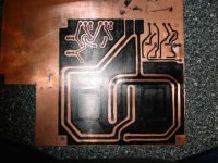
Am already working on the PC board patterns for the project, and I'll probably end up with slightly more voltage for the drivers than for the chip's preamp. But, as I said above, this should help improve sound at higher power levels by causing the preamp to clip before the drivers do.
O d d O n e
Seperating input and output stages power supplies is usually a good thing. Some amps use a slightly higher supply
voltage for the input stages. You would need to add seperate bridge rectifiers and caps to give seperate input stage supplies.
Yeah, I would need to add separate rectification/filtration and that's not at all going to pose a problem.
Plus, it looks like I'll be hitting the driver section with ~#17736VDC and the preamp section with about ~#17730VDC, so there'll be a slight self-limiting effect as the preamp maxes out before the drivers start to get into their higher-distortortion output levels.
Heatsink - probably needs fan forced air for reliable full power operation - in my books fan cooling is required - IME keeping things as cool as possible sounds nicer. Plenty of quite high power modern shelf systems use fan forced air on a lesser heatsink. 3" 12Vdc fans are cheap and are quiet, especially if you reduce the supply voltage to them.
I figured I'd need at least one fan, and I'll duct the HS fins to get better thermal transfer into the moving air.
Plenty of commercial hifi amps run at the most +and - 6800 uF supply capacitance, so the additional 3300 uF caps you mention should be well adequate.
I have eight 3300s here, waiting for their time in the sun. I'll probably use them for transient damping on the boards for the TDAs and order another eight or so for the supply for the preamp sections.
TDA7293 TDA7294 are my favourites for IC power amp applications.
I asked the wellknown constructor of Parasounds legendary Phono-amp
sorry I can not remember his name (I am getting old, you know)
He said, that TDA729x was a good choice.
He had experience of some friend's construction with the IC.
And was pleased.
In this PDF is circuit suggestions and a BOARD layout.
If I could decide, I would use the supply-pin 7,8 for separate supply to the input stage.
There is never any good reason NOT TO protect the input stage from the output stage.
This common very bad pratice, comes from the commercial designs.
They would like to build anything to minimize components,
to keep PROFITS margins MAXIMIZED.
In this case SIMPLE is not GOOD at all. IT IS BAD.
A separate rectifier and smooting circuit, is the least I would like to use.
I would advocate a higher voltage to the transistors that drives
the Output Transistors. Say 5-10 Volts more, at full Output.
I assume class A operation.
Am already working on the PC board patterns for the project, and I'll probably end up with slightly more voltage for the drivers than for the chip's preamp. But, as I said above, this should help improve sound at higher power levels by causing the preamp to clip before the drivers do.
O d d O n e
This last part was more about discrete amplifier designs in general,There is never any good reason NOT TO protect the input stage from the output stage.
This common very bad pratice, comes from the commercial designs.
They would like to build anything to minimize components,
to keep PROFITS margins MAXIMIZED.
In this case SIMPLE is not GOOD at all. IT IS BAD.
A separate rectifier and smooting circuit, is the least I would like to use.
I would advocate a higher voltage to the transistors that drives
the Output Transistors. Say 5-10 Volts more, at full Output.
I assume class A operation.
not related to using TDA7293.
When building a class A amp, using lower Voltage for Output
will minimize the losses in form of heat.
At the same time the drivers have a healthy Collector-Emitter
voltage margin to work more linear.
One other application for the separated power supply is the possibility of using a transistor pair to 'bootstrap' the output voltage. That application is listed in the datasheet as the 'high efficiency' mode. Good for subs or similar where slightly higher distortion figures will be at least tolerable. Not very good for hifi.
Of course running the supply rails lower keep the amp more linear, as halojoy pointed out. lower distortion, less heat dissipation...
Of course running the supply rails lower keep the amp more linear, as halojoy pointed out. lower distortion, less heat dissipation...
-This is the man I asked about TDA7293:halojoy said:TDA7293 TDA7294 are my favourites for IC power amp applications.
I asked the wellknown constructor of Parasounds legendary Phono-amp
sorry I can not remember his name (I am getting old, you know)
He said, that TDA729x was a good choice.
He had experience of some friend's construction with the IC.
And was pleased.
"Parasound design consultant John Curl is a legend among audiophiles and electronic engineers.
Curl has designed some fantastically expensive products on his own, such as the Vendetta Research phono preamplifiers. In 1974, he sparked the high-end revolution when he designed the groundbreaking Mark Levinson JC-2 preamplifier."
OddOne,
I had posted a thread a few months ago using this chip (search on TDA7293 to locate it) about separating the power supply pins . I tried a simple method of decoupling the input PS from the output stage PS: adding a small resistor like 10 ohm (I went down to 2 ohms or so; after starting at 100 ohms) combined with a capacitor.
All tests resulted in spectacular frying of the resistors and blown chips. It seems like the current demand on the input stage was disproportiate. I gave up and left the two stages PS in parallel as described in the spec sheets.
Good luck, and tell me if you get it to work--and how you did it,
Robert
rljones' experiences with TDA7293v
this is the thread that rljones refer to
http://www.diyaudio.com/forums/showthread.php?s=&threadid=3857
That oscillation? is not what we would expect
from such a decoupling of the stages' power supplies.
A separate rectifier is what I would use.
4 diodes cost not much and a one elyt, eventually a little resistor.
And close to pin a smaller cap connected to the best place of the groundplane.
It is very important to connect capacitors to the best place in the earthing. Otherwise they can introduce "spikes, signal" into a bad place.
Sometimes it is even preferable not to connect them to ground,
but from V+ to V-.
This goes for OP-amplifiers too, sometimes. 🙂
"Spicks And Specks" Bee Gees (single)
http://www.absolutelyric.com/a/view/Bee Gees/Spicks And Specks/
Worked up a test board for one channel based on the spec sheet's test circuit, attached the TDA7293 via short (8" or so long) umbilical cabling so I could mount the chip and heatsink wherever. And, apparently either miswired or shorted something in the process without realizing it. Applied power and POW!! Burn marks on the heatsink's anodizing.
But I found that my supply will put out around + and - 42VDC with a load on it, with the chip wanting no more than 50 above/below GND. (It's rated for a 60-60 split supply but apparently the bootstrap capacitor holds it to 50-50.)
Glad I bought ten of the darn things. 😀
And yes, I did search fot "TDA729x" and did already see rljones' thread on splitting the supply by section.
oO
Update:
I redid my umbilical to a new 7293, and made sure all was well with all connections. I am showing 89VDC across both signal and driver power pins, which is within spec. (The supply's sweet spot with no signal into the amp seems to stabilize at plus and minus 44.5 volts.)
Connected a signal source, applied power, got nothing out. A true-RMS DMM across the output showed near zero, and the speaker emitted nary a sound. Input signal is usable, the voltages are where and as high as they should, and everything looks to be connected properly, but there is still no joy.
I copied the test/application circuit in figure 1 of the 7293's spec sheets, but apparently either that circuit no workie as-is or I missed something in my initial construction. (I'd lay odds I screwed up somewhere. 😀) I'll probably etch a board and retry it tomorrow.
EDIT: Just spotted my screwup - I'm grounding the mute and standby pins instead of bringing them to +Vs. I ad the damn thing stuck on mute.
 Oh well, at least it's an easy fix...
I did find out something though - you do NOT want to accidentally short the mute or standby pins to ground as it destroys the 7293 immediately. I have the mute/stby pins temporarily hooked to a switch that seems to have an affinity for swinging round and tapping the heatsink I have the 7293 attached to - POW! no more 7293. (Taped that mofo up so that won't happen again.)
So, two of the ten 7293s I started with have been sacrificed to the gods of experimentation... Hopefully the third time will be the charm.
oO
I redid my umbilical to a new 7293, and made sure all was well with all connections. I am showing 89VDC across both signal and driver power pins, which is within spec. (The supply's sweet spot with no signal into the amp seems to stabilize at plus and minus 44.5 volts.)
Connected a signal source, applied power, got nothing out. A true-RMS DMM across the output showed near zero, and the speaker emitted nary a sound. Input signal is usable, the voltages are where and as high as they should, and everything looks to be connected properly, but there is still no joy.
I copied the test/application circuit in figure 1 of the 7293's spec sheets, but apparently either that circuit no workie as-is or I missed something in my initial construction. (I'd lay odds I screwed up somewhere. 😀) I'll probably etch a board and retry it tomorrow.
EDIT: Just spotted my screwup - I'm grounding the mute and standby pins instead of bringing them to +Vs. I ad the damn thing stuck on mute.
Oh well, at least it's an easy fix...I did find out something though - you do NOT want to accidentally short the mute or standby pins to ground as it destroys the 7293 immediately. I have the mute/stby pins temporarily hooked to a switch that seems to have an affinity for swinging round and tapping the heatsink I have the 7293 attached to - POW! no more 7293. (Taped that mofo up so that won't happen again.)
So, two of the ten 7293s I started with have been sacrificed to the gods of experimentation... Hopefully the third time will be the charm.
oO
Of course it is good to know how all the pins work.
First the body of TDA7293 (like many power amp IC)
is internally connected to V-, same as pin 8, signal V-
So we can not have the IC mounted uninsulated
and use the heatsink in connetion to GROUND.
Standby GND - the groundreference for MUTE and STANDBY pins
is pin 1. This is normally connected to 0 V = POWER GROUND
For pin 9 and 10, see figure 6.
You see Standby have = 20kohm
and mute have 10kohm+30kohm= 40 kohm
You also see in fig 6.
how to "Play" and "Standby"
Pin 4 MODE should be connected to GND for Master mode, using one TDA7293.
Hope I have got it correctly, read more!
halojoy:
Knowing what does what isn't a problem - I've been doing this stuff since I was twelve. What -is- a problem is when you look right at the secret and your brain doesn't catch its import, which is what my problem was. I looked right at the spec sheets showing the mute and standby pins tied to +Vmute and +Vstby (why they didn't put +Vs is beyond me) and failed to realize what it was showing.
Even the best experts in the world screw up from time to time. 😀
That said...
Rewired the mute/standby to switch to +Vs, replaced the 7293, and all is working. Amazing what a difference not perma-grounding the mute/standby pins makes! 😀
Now I need to find a source for kapton film in a suitable thickness (a couple mils or so) to cut some insulators from, and I can start working on a paralleling a second 7293 to improve the low-load-impedance capacity of the project amp. Wowzers, the little joker gets hot after a while!
I have what I term the heatsink from hell - a fifteen pound, foot-wide finned-aluminum monster that came out of a thousand-watt amplifier someone had abused, blew up, and tossed. I'm debating mounting four 7293s in it as it's definitely got enough game to handle a couple hundred watts of dissipated heat from a quartet of 7293s. That'll cure the heat issue even if nothing else can. 😉
I've also been thinking about the drive supply vs. signal supply issue. I'm debating picking up another rectifier bridge and a few more capacitors and making use of the currently not connected 50VCT windings on my supply's transformer. I figure if I connect the center tap to the ground of the driver supply I should be able to run the signal off this separately rectified and otherwise isolated source and clean up the output some. Plus, since the 50VCT winding on my transformer can sink 4 amps or so I should have more than enough current to drive the signal stages of multiple 7293s without causing a sharp increase in distortion. And, I'll be able to add transient suppression capacitors hither and yon to further smooth out the supply to the signal side of the 7293.
oO
Glad it works well, OddOne!
That heatsink seems like Gold.
I mute now
and standby for more.
It is like the days before christmas
when we were small 🙂
That heatsink seems like Gold.
I mute now
and standby for more.
It is like the days before christmas
when we were small 🙂
Picture time!
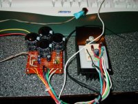
Here's the test amp, the power supply and support circuitry at left and the TDA7293 on the heatsink at right. The wiring is not separated out (read: power and signal lines are all in one bundle) for better quality, as it's not important yet - this was a feasibility test.
With a 4-ohm load being driven with about 20 watts, the heatsink is hot to the touch after about two minutes.
oO
Attachments
Next picture:
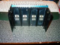
This is the heatsink I mentioned at the outset of this thread, with four TDA7293s attached. The blue object is a 6" engineer's scale, for a size comparison. The heatsink weighs about 3 lbs.
Given how hot the heatsink gets that I have one 7293 bolted to, I'm beginning to have my doubts that it wil be adequate for four of them in two-by-two paralleled operation...
oO
Attachments
Last picture for now:
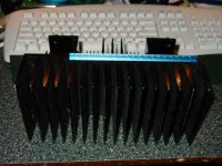
This is what I might use instead - the monster heatsink I mentioned earlier. It is a beast, too - I kicked it once in the dark when it was on the floor and it split my toe open, toenail and all! (Still have the scar from the encounter.)
I don't have any doubts that this beast can take the heat from four 7293s...
oO
Attachments
Heat is the price you pay.
Heat is the price you pay
for that relatively high supply voltage.
The good thing is that you with best heatsinks
will have a lot of power.
And hopefully a great sounding amplifier.
How high voltage gain are you using?
Heat is the price you pay
for that relatively high supply voltage.
The good thing is that you with best heatsinks
will have a lot of power.
And hopefully a great sounding amplifier.
How high voltage gain are you using?
Right now I have it set to 30dB as the spec sheet's test/app circuit has it listed. I might play with it a bit once I get a better support PC board etched and populated.
I'm also checking into a forced-convection heatsink from Aavid - if they send me an engineering sample of it (it's nice being the owner of an R&D company!) I'll see how well it handles the heat, as it'd be a lot easier to mount than the big monster.
oO
I'm also checking into a forced-convection heatsink from Aavid - if they send me an engineering sample of it (it's nice being the owner of an R&D company!) I'll see how well it handles the heat, as it'd be a lot easier to mount than the big monster.
oO
- Status
- Not open for further replies.
- Home
- Amplifiers
- Solid State
- Qs about a two-channel quad paralleled TDA7293 amp...