Part 2
The power supply
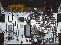
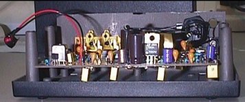
The standard Digit comes with a single wall-plug style 12v DC unregulated supply, providing approx. 17v unloaded. I measured a current consumption of approx. 150mA from my Digit (non-OPTO model). This single supply feeds both analogue and digital sections.
The plug-in device is well made featuring a small transformer, bridge rectifier and single smoothing cap and is clearly a common component across a wide range of other QED products (NOTE: QED's main specialism has always been cabling, distribution units and multi-room systems).
Inside the Digit this 12v unregulated supply is divided. It feeds a single 7805 fixed voltage regulator, with 470uf/25v smoothing caps, to provide the necessary regulated 5v for the LC resonator, 7224 and 7323 chips. The second feed from the 12v supply uses a simple Zener diode (D2) to provide a regulated 11v across the NE5532, giving a supply +5.5v supply.
It's worth noting that while the Digit uses the minimum of supply regulation and diversification, extensive use is made of low impedance tantalum bead caps to provide decoupling to all components. There are 15 such 10uf/16v caps, plus some additional 50uF electrolytics providing additional smoothing to the subsections of the 7323 DAC chip.
The 7323 is a 44 pin chip on the underside of the board. It is highly complex and it has separate analogue and digital supplies (Digital pins 22, 23 Analogue pins 11, 39 & 43). Decoupling between the digital and analogue supply pins is provided by 2 * 50uf Caps and 2 small inductors, resembling small carbon based resistors.
It has an onboard voltage reference (optional) with it's own supply pin (Pin 11) and smoothing cap pin (pin 15). It also features onboard OpAmps, 2 sets, the first to provide current to voltage conversion (pins 10, 44 used by the Digit), the second to drive the output (pins 12, 13, 14, 40, 41, 42 disabled in the Digit - primarily used in Discman type applications of the chip set).
One of the main areas of tweaks to the Digit involve improving the power supply and it's regulation.
--------------------------------------------------------------------------------
DIY Options
WARNING: ONLY UNDERTAKE ANY MODIFICATIONS IF YOU HAVE A GOOD UNDERSTANDING OF ELECTRICITY AND ELECTRONICS. MODIFICATIONS WILL INVALIDATE YOU WARANTEE, IF SOMETHING GOES WRONG IT'S UNLIKELY YOU WILL GET IT FIXED. ELECTRICAL VOLTAGES CAN BE FATAL. ALWAYS TAKE EXTREME CARE.
ALTHOUGH WE WERE VERY CAREFUL WHILE WRITING THERE COULD BE FAULTY DESCRIPTIONS ON THESE PAGES. SO YOU SHOULD BE AWARE ABOUT WHAT YOU ARE DOING.
Dismantling the Digit
The Plastic case is held together by 4 screws accessible from the underside. Removing these enables you to separate the plastic box into its top and bottom sections.
The circuit board is connected to the lower half. When reassembling do not be tempted to overtighten these screws as they will strip the thread from the holes in the top section, and no longer bind. I speak from experience as my Digit is now held together by 2 audio-grade-polymer-damping-loops ("Rubber bands").
There are minor differences between types of Digit. Early models had the red LED mounted on the board and visible through the semi-dark Perspex front. This kind is the easiest to take apart. My later model has no Perspex front, the led is glued over a small hole in the front of the box. This means that 2 fine wires link the LED to the circuit board. This adds more complication as to dismantle properly this will need to be disconnected. If you expect to be doing much work, some form of small cable plugs and sockets would provide a simple way of breaking and making the link every time you dismantle. Purists might say the LED isn't needed, but it's nice to know when there is power, especially as the DC plugs and sockets are not very good.
To remove the circuit board remove another four screws which hold the circuit board to the base + a further 2 screws which hold it to the back. >From here you should be able to remove the board by lifting the front and sliding the 3 RCA sockets out of there rear holes. The Digit OPTO is more tricky due to the additional TOSLINK Optical socket on the circuit board.
Power supply changes
Soon after the launch of the Positron uprated power supply, the UK HiFi Magazine "HiFi World" published an article in it's June 1993 Supplement detailing how to split the power supply tracks in a Digit, remove the zener diode(D2), load resistor(R37), fit an extra socket and run the device from 2 Positrons, one supplying the Digital section, one the analogue. This is not quite true, as splitting the tracks as detailed by Hi Fi World separates the supply to the output OpAmp from that of the DAC, receiver and Phase Locked Loop (PLL). The 7323 has both analogue and digital sections, which in more expensive DAC's, are further divided (see references). However the results of this simple modification raised the sound quality of the humble Digit into the realms of DAC's at many times the price.
Since the Digit or Positron are no longer manufactured it may be difficult to find either single or pairs of Positrons on the market. An alternative approach is to use sealed lead acid batteries which are available in 12V versions from Maplin, Tandy (Radio Shack) and Radio control hobby shops. One popular brand is Yuasca. These units are sealed and so will not spill acid or give off gas. You will also require a suitable charger (see DIY Lead Acid Battery Charger). A battery provides a near-perfect power supply. It is already DC, is noise-free (mains & rectifier originated), has low impedance and hence can deliver instantaneous high current on demand, typically >30Amps.
1) So if you have a Digit a simple first step is to run it from a single lead acid, while keeping the original plug PSU for standby. You need to make up a suitable cable, with a DC socket on one end and minature spade/lug connectors on the other to attach to the battery. If you are lazy like me, Tandy do a 12v car supply lead with good heavy gauge cable, sealed DC plug, and a cigar-lighter plug on the other end. Just remove this, and replace with the battery connectors. This improves the bass and soundstage, though is quite subtle.
WARNING: Be careful to ensure the -ve & +ve polarity arecorrect for the Digit. DC plug center is +ve.
2) The Zener diode (D2) inside the digit provides shunt regulation & ensures the voltage across the OpAmp never exceeds the rating for the two 10uF/16v tantalum bead smoothing caps. This is because the standard plug PSU is unregulated. However Zeners are notoriously noisey, and if only using a 12v battery, the voltage will not be a problem. Therefor you can remove D2 and its load resistor, the latter replaced by a wire link.
WARNING: You should not now use the standard unregulated psu - batteries or a regulated 12v psu only.
3) Moving to 2 supplies: By this stage you have a single lead acid powered digit. To move to twin supplies as per HiFi World is very simple. Drill a hole in the back panel and mount a second DC socket, above the existing one is a good place. Next remove the wire link (LK) at the rear-center of the circuit board. Run a wire from the new DC plug enter (+ve) to the hole from the link nearest the front of the board. Run a second lead from the socket (-ve) to a convenient ground. The zener removed earlier leaves a convenient hole.
You have now split the supplies. IMHO this stage represents the largest step forward in the Digit performance. What follows is also worthwhile, but for the maximum benefit, for the minimum work then this stage is probably the one to go for, especially if your soldering iron skills are limited. The sound stage appears larger, bass is better (deeper) and everything sounds more effortless. I was reluctant to take this step at first as the HiFi World article described the sound as "more detailed" and "harder" - both euphamisms for bightness I feel. This wasn't the case. The sound is just better, more natural and effortless, and not brighter, harder (for us anyway).
Once you have split the supply as detailed above there are a number of further refinements that can be made.
Within the Digital section the regulation to +5v is provided by a standard 7805 fixed volt regulator, either side of which is a 470uf/25v Electrolytic cap. The regulator can be replaced by the higher spec Linear Technologies LT323AT, which is also higher current rated. It's identical in size and pin arrangements. The 2 caps can be replaced by equivalent ELNA RSH caps or OSCONS. The OSCONS are a little bigger. I use an ELNA on the input and a lower value (100uf) OSCON on the output. Both caps can be bypassed under the board with suitable low value MKP caps, I use 0.01uF Polycarbonates from MAPLIN.
The Digital supply track follows the edge of the circuit board, presumably as a wise means of keeping noise low. 3 * 50uf/10v caps are used to provide extra decoupling between stages. One is by the 7242 chip, the other 2 are around the 7323 chip. All are miniature can type and can be better replaced with identical value OSCON caps, which are the same size and fit well. Agin each of these can also be bypassed under the board with small value MKP's.
Do not remove any of the tantalum beads in the Digital section, these provide extra low impedance smoothing.
All of the above provides better power supply decoupling throughout the Digital section of the DAC.
The power supply
The standard Digit comes with a single wall-plug style 12v DC unregulated supply, providing approx. 17v unloaded. I measured a current consumption of approx. 150mA from my Digit (non-OPTO model). This single supply feeds both analogue and digital sections.
The plug-in device is well made featuring a small transformer, bridge rectifier and single smoothing cap and is clearly a common component across a wide range of other QED products (NOTE: QED's main specialism has always been cabling, distribution units and multi-room systems).
Inside the Digit this 12v unregulated supply is divided. It feeds a single 7805 fixed voltage regulator, with 470uf/25v smoothing caps, to provide the necessary regulated 5v for the LC resonator, 7224 and 7323 chips. The second feed from the 12v supply uses a simple Zener diode (D2) to provide a regulated 11v across the NE5532, giving a supply +5.5v supply.
It's worth noting that while the Digit uses the minimum of supply regulation and diversification, extensive use is made of low impedance tantalum bead caps to provide decoupling to all components. There are 15 such 10uf/16v caps, plus some additional 50uF electrolytics providing additional smoothing to the subsections of the 7323 DAC chip.
The 7323 is a 44 pin chip on the underside of the board. It is highly complex and it has separate analogue and digital supplies (Digital pins 22, 23 Analogue pins 11, 39 & 43). Decoupling between the digital and analogue supply pins is provided by 2 * 50uf Caps and 2 small inductors, resembling small carbon based resistors.
It has an onboard voltage reference (optional) with it's own supply pin (Pin 11) and smoothing cap pin (pin 15). It also features onboard OpAmps, 2 sets, the first to provide current to voltage conversion (pins 10, 44 used by the Digit), the second to drive the output (pins 12, 13, 14, 40, 41, 42 disabled in the Digit - primarily used in Discman type applications of the chip set).
One of the main areas of tweaks to the Digit involve improving the power supply and it's regulation.
--------------------------------------------------------------------------------
DIY Options
WARNING: ONLY UNDERTAKE ANY MODIFICATIONS IF YOU HAVE A GOOD UNDERSTANDING OF ELECTRICITY AND ELECTRONICS. MODIFICATIONS WILL INVALIDATE YOU WARANTEE, IF SOMETHING GOES WRONG IT'S UNLIKELY YOU WILL GET IT FIXED. ELECTRICAL VOLTAGES CAN BE FATAL. ALWAYS TAKE EXTREME CARE.
ALTHOUGH WE WERE VERY CAREFUL WHILE WRITING THERE COULD BE FAULTY DESCRIPTIONS ON THESE PAGES. SO YOU SHOULD BE AWARE ABOUT WHAT YOU ARE DOING.
Dismantling the Digit
The Plastic case is held together by 4 screws accessible from the underside. Removing these enables you to separate the plastic box into its top and bottom sections.
The circuit board is connected to the lower half. When reassembling do not be tempted to overtighten these screws as they will strip the thread from the holes in the top section, and no longer bind. I speak from experience as my Digit is now held together by 2 audio-grade-polymer-damping-loops ("Rubber bands").
There are minor differences between types of Digit. Early models had the red LED mounted on the board and visible through the semi-dark Perspex front. This kind is the easiest to take apart. My later model has no Perspex front, the led is glued over a small hole in the front of the box. This means that 2 fine wires link the LED to the circuit board. This adds more complication as to dismantle properly this will need to be disconnected. If you expect to be doing much work, some form of small cable plugs and sockets would provide a simple way of breaking and making the link every time you dismantle. Purists might say the LED isn't needed, but it's nice to know when there is power, especially as the DC plugs and sockets are not very good.
To remove the circuit board remove another four screws which hold the circuit board to the base + a further 2 screws which hold it to the back. >From here you should be able to remove the board by lifting the front and sliding the 3 RCA sockets out of there rear holes. The Digit OPTO is more tricky due to the additional TOSLINK Optical socket on the circuit board.
Power supply changes
Soon after the launch of the Positron uprated power supply, the UK HiFi Magazine "HiFi World" published an article in it's June 1993 Supplement detailing how to split the power supply tracks in a Digit, remove the zener diode(D2), load resistor(R37), fit an extra socket and run the device from 2 Positrons, one supplying the Digital section, one the analogue. This is not quite true, as splitting the tracks as detailed by Hi Fi World separates the supply to the output OpAmp from that of the DAC, receiver and Phase Locked Loop (PLL). The 7323 has both analogue and digital sections, which in more expensive DAC's, are further divided (see references). However the results of this simple modification raised the sound quality of the humble Digit into the realms of DAC's at many times the price.
Since the Digit or Positron are no longer manufactured it may be difficult to find either single or pairs of Positrons on the market. An alternative approach is to use sealed lead acid batteries which are available in 12V versions from Maplin, Tandy (Radio Shack) and Radio control hobby shops. One popular brand is Yuasca. These units are sealed and so will not spill acid or give off gas. You will also require a suitable charger (see DIY Lead Acid Battery Charger). A battery provides a near-perfect power supply. It is already DC, is noise-free (mains & rectifier originated), has low impedance and hence can deliver instantaneous high current on demand, typically >30Amps.
1) So if you have a Digit a simple first step is to run it from a single lead acid, while keeping the original plug PSU for standby. You need to make up a suitable cable, with a DC socket on one end and minature spade/lug connectors on the other to attach to the battery. If you are lazy like me, Tandy do a 12v car supply lead with good heavy gauge cable, sealed DC plug, and a cigar-lighter plug on the other end. Just remove this, and replace with the battery connectors. This improves the bass and soundstage, though is quite subtle.
WARNING: Be careful to ensure the -ve & +ve polarity arecorrect for the Digit. DC plug center is +ve.
2) The Zener diode (D2) inside the digit provides shunt regulation & ensures the voltage across the OpAmp never exceeds the rating for the two 10uF/16v tantalum bead smoothing caps. This is because the standard plug PSU is unregulated. However Zeners are notoriously noisey, and if only using a 12v battery, the voltage will not be a problem. Therefor you can remove D2 and its load resistor, the latter replaced by a wire link.
WARNING: You should not now use the standard unregulated psu - batteries or a regulated 12v psu only.
3) Moving to 2 supplies: By this stage you have a single lead acid powered digit. To move to twin supplies as per HiFi World is very simple. Drill a hole in the back panel and mount a second DC socket, above the existing one is a good place. Next remove the wire link (LK) at the rear-center of the circuit board. Run a wire from the new DC plug enter (+ve) to the hole from the link nearest the front of the board. Run a second lead from the socket (-ve) to a convenient ground. The zener removed earlier leaves a convenient hole.
You have now split the supplies. IMHO this stage represents the largest step forward in the Digit performance. What follows is also worthwhile, but for the maximum benefit, for the minimum work then this stage is probably the one to go for, especially if your soldering iron skills are limited. The sound stage appears larger, bass is better (deeper) and everything sounds more effortless. I was reluctant to take this step at first as the HiFi World article described the sound as "more detailed" and "harder" - both euphamisms for bightness I feel. This wasn't the case. The sound is just better, more natural and effortless, and not brighter, harder (for us anyway).
Once you have split the supply as detailed above there are a number of further refinements that can be made.
Within the Digital section the regulation to +5v is provided by a standard 7805 fixed volt regulator, either side of which is a 470uf/25v Electrolytic cap. The regulator can be replaced by the higher spec Linear Technologies LT323AT, which is also higher current rated. It's identical in size and pin arrangements. The 2 caps can be replaced by equivalent ELNA RSH caps or OSCONS. The OSCONS are a little bigger. I use an ELNA on the input and a lower value (100uf) OSCON on the output. Both caps can be bypassed under the board with suitable low value MKP caps, I use 0.01uF Polycarbonates from MAPLIN.
The Digital supply track follows the edge of the circuit board, presumably as a wise means of keeping noise low. 3 * 50uf/10v caps are used to provide extra decoupling between stages. One is by the 7242 chip, the other 2 are around the 7323 chip. All are miniature can type and can be better replaced with identical value OSCON caps, which are the same size and fit well. Agin each of these can also be bypassed under the board with small value MKP's.
Do not remove any of the tantalum beads in the Digital section, these provide extra low impedance smoothing.
All of the above provides better power supply decoupling throughout the Digital section of the DAC.
part 3
The output circuit
Most CD players and DAC's use a number of OpAmps in their outputs. Most DAC chips produce an output of current steps which must be converted into voltage steps. Hence there are 2 primary functions in a CD player output, to convert current to voltage, and to drive the output. The first function requires OpAmps of exceptionally fast slew rate, and a lot of tweakers have improved the performance of CD players by replacing the OpAmps with better spec devices from Analogue Devices, Burr Brown and Harris.
In the case of the Digit, this first critical current-voltage conversion is done "on chip" by an internal pair of OpAmps within the 7323. Hence the Digit only requires a single OpAmp per channel to drive it's output, provided by one dual NE5532. Decent polystyrene caps are used throughout the de-emphasis network between the DAC and the OpAmp.
Before examining the OpAmp itself, it's worth looking at the power supply to it. The NE5532 is provided with 2 Tantalum bead 10uF/16v caps to decouple the DC supply. In the standard Digit this is provided by the 11v Zener, in modified form this is straight off the Analogue Lead acid. Space is tight but it's possible to replace these 2 caps with 47uF/16v OSCONS. It's a little tight and the caps lean a little but it works.
The remainder of the output circuit involves 2 more critical caps per channel, a 100uF/25v electrolytic cap to block any DC and a 4700pf ceramic to provide a degree of HF roll off ("Smoother sound").
Some brave souls would question whether the DC blocking caps are necessary, but I like to play safe. Ideally this cap would be best replaced with a large value Polypropylene , but space is again VERY tight and no film caps will fit. Next best thing is a non-polarised electrolytic. This is what Marantz use in their SE edition CD players, usually 2 * 220uF caps back-to-back i.e. achieving a 110uF bipolar. This is still large though. I noticed that there was a Blackgate 100uF bipolar sold, but the UK supplier is out of stock and the price was 25 pounds UK sterling for a single cap. In the end I settled for a Nichicon Muse 10uF/10V bipolar. These just about fit with one upright and one on it's side. This value is still high enough to have no real effect on the bass roll-off.
I noticed a lot more detail with the bipolar than the original standard caps, though if you like a warmer sound you might like to leave the older caps in. Either way you can also put bypass caps under the board (0.01uF MKP). The 4700pF Ceramics set the high frequency roll off. I replaced these with radial Polystyrene's of the same value. These just about fit Minor improvement (possibly).
The output OpAmp itself provides a nice field for experimentation. First you should unsolder the NE5532 and substitute a gold-plated, turned-pin DIL-8 socket. There is a little mark on top of the OpAmp which shows you its direction. Be shure to remember this direction because you can't use these chips the other way around. If you destroy the OpAmp while unsoldering you should buy a new one for future comparisons (it's very cheap).
The NE5532 is a dual OpAmp / it amplifies the signals of the left and right channel. It's very easy to replace it with another dual OpAmp which has to be pin-compatible and designed to work in an output stage. The Digit has to be switched off before replacement. Be careful while pressing the new OpAmp into the socket because the pins easily get broken. There are a of possible replacements for the standard IC (the OPA2604 is my favourite).
If you want more you should try two single OpAmps instead of one dual. To do so you need a U-form adaptor for the connection between your DIL-8 socket and the two 8-pin OpAmps (I think Audio Synthesis sells them). A single OpAmp with a high reputation is the AD797 which I never tried because I directly chose the even more complicated solution of an AD744/AD811-combination (the original NE5532 is replaced by 4 OpAmps !). Sonically this one is the best, at least for ME.
You have to be aware that every chip has a sonic signature of its own and you will have to find YOUR PESONAL solution here. As Dominic Todd wrote in Hifi-World 08/1998 "One listener's 'bright and vivid' is another's 'grainy and harsh'". Jonathan, for example, still uses the standard OpAmp because all its replacements were too bright for him. You should go back to the NE5532 from time to time to check that you really achieved an improvement. Be aware that OpAmps need a little time to break in though.
--------------------------------------------------------------------------------
Tests
Hi-Fi World, May 1992
Hi-Fi News, June 1992
Audiophile, July 1992
What HiFi ?, June and December 1992
Excellect work
Well done Jives!
This is great for all of us with early Bitstream machines. Much of this applies to my CD624.
Well done Jives!
This is great for all of us with early Bitstream machines. Much of this applies to my CD624.
a pleasure, but the real respect must go to Dieter Strecker for hosting the website in the first place, building the pages and digging up an old backup from years ago. Also apologise for my poor photography, bit hard to tell which are oscons and which are Elnas.
Dieter also built a Lead Acid charger
--------------------------------------------------------------------------------
Charger for 12V Lead Acid Batteries
This charger delivers a constant voltage of 13,8V which is the optimum for charging 12V Lead Acids. During the charging process the Lead Acid itself sets the current (the current decreases while charging). The batteries need charging when their voltage drops below 12V. After charging their voltage will be approximately 12,8V. The circuit described above is able to deliver up to 1,5A of current. It is also possible to charge several Lead Acids in parallel but then it will take longer until the batteries are charged. The voltage regulator (LM317) gets very hot and so needs a cooling surface. The circuit needs an input voltage of 17-30V DC which could be supplied by a simple design like this:
The parts of this design should be able to handle the maximum current of the following chargers. C should have a value of (1000uF * max. current A).
Attachments
Schematics?
Has anyone had any luck in locating circuit diagrams for the Digit or other good implementations of the SAA7321 or SAA7323 chips?
Maybe some close up photos of the DAC, its surrounging components and output stage would be useful. I can provide some diagrams, etc. of Philips machines using this DAC - if anyone is interested.
Thanks again Jives
Any idea of the values of the components forming the LPF and analogue stage?
The CD624 uses the onboard opamps - and I'm looking for a good way to get around them. Maybe copying the Digit's layout would be good.
If any of you Digit owners are exploring this area of your circuit board - it would be great if you could take a note of the components between pins 10 and 44 to the output RCAs.
I had a dia few years back, I got rid of the opamp all together and used a passive low pass filter. This I thought was the best solution although I lost a lot of output (but you can just turn the volume up or perhaps put a discrete or tube gain stag on the end. Sorry cant remember the output values
A related note. I just replaced a bunch of AC coupling caps for DC blocking in my Quad 44. I used the bipolar eletrolytics offered by RS components (www.rswww.com) from a brand Nitai. These are small yellow cans. The 100uF/16v is probably small enough to fit in the digit to replace the 2 DC blocking caps. Also they costs pennies. Sound is very good IMHO.
Hi,
I built a little 11.28986 Mhz oscilator module to feed the dac chip. From looking at the trace the SAA7274P supplied the clock to the dac.
Problem a:- However, when I connected the clock module (after cutting trace to saa7274P pin24) I could hear clear music but with some overlaid distortion. 🙁
Ground noise or timing issue (needs a pll?) ?
Does anyone know how the 11.2896 MHz clock is produced in the QED digit ? Looks to me like a ceramic oscilator based around a 74HCU04 IC (IC2) or regenerated from input spdif.
Anyway I have tapped the trace to pin 24 of SAA7274P to a RCA socket so eventually I can feed the clock back to a transport.
As for vref....
I replaced the vref decoupling cap to an 220uf oscon + 0.1uf polystrene which made a huge difference to the bass see http://www.diyaudio.com/forums/showthread.php?postid=296481#post296481
I also added a wrong reference ZRC250 (2.5v instead of 5V) and I connected it upto to Vdd vref (pin 15) , and ground. At first it oscillated due to the Oscon but it works ok now.
At pin 15 I measured 2.5V, and at pin 16 I have 1.25V which makes sense from the datasheet but I get music....
I'm guessing the vref is only used for an external op amp IV converter which isn't used in the QED Digit so I can get away with the wrong vref value. This charging makes sense as when I disconnected L2 the dac continued playing for a few seconds, and then distorted.
Kind regards,
Ashley.
I built a little 11.28986 Mhz oscilator module to feed the dac chip. From looking at the trace the SAA7274P supplied the clock to the dac.
Problem a:- However, when I connected the clock module (after cutting trace to saa7274P pin24) I could hear clear music but with some overlaid distortion. 🙁
Ground noise or timing issue (needs a pll?) ?
Does anyone know how the 11.2896 MHz clock is produced in the QED digit ? Looks to me like a ceramic oscilator based around a 74HCU04 IC (IC2) or regenerated from input spdif.
Anyway I have tapped the trace to pin 24 of SAA7274P to a RCA socket so eventually I can feed the clock back to a transport.
As for vref....
I replaced the vref decoupling cap to an 220uf oscon + 0.1uf polystrene which made a huge difference to the bass
see http://www.diyaudio.com/forums/showthread.php?postid=296481#post296481I also added a wrong reference ZRC250 (2.5v instead of 5V) and I connected it upto to Vdd vref (pin 15) , and ground. At first it oscillated due to the Oscon but it works ok now.
At pin 15 I measured 2.5V, and at pin 16 I have 1.25V which makes sense from the datasheet but I get music....
I'm guessing the vref is only used for an external op amp IV converter which isn't used in the QED Digit so I can get away with the wrong vref value. This charging makes sense as when I disconnected L2 the dac continued playing for a few seconds, and then distorted.
Kind regards,
Ashley.
Digit output impedance?
Hi guys,
Dunno if anybody will read this old thread, but I just have a quick question... would anyone happen to know the output impedance of a 'standard' Digit? Will it drive a 10k volume control?
Cheers!
Hi guys,
Dunno if anybody will read this old thread, but I just have a quick question... would anyone happen to know the output impedance of a 'standard' Digit? Will it drive a 10k volume control?
Cheers!
Bumping an OLD thread I know.. I've got one of these with a Positron and I'm about to start playing with it to see what I can acheive. Just wondering if anyone has one still and has anything to add to the comprehensive list on P3?
cheers!
James.
cheers!
James.
Bumpety bump🙂Bumping an OLD thread I know.. I've got one of these with a Positron and I'm about to start playing with it to see what I can acheive. Just wondering if anyone has one still and has anything to add to the comprehensive list on P3?
cheers!
James.
I am waiting for an early digit to arrive and I am about to tinker as per this thread.
I have the modded chinese ak4396 DAC at the moment and I'm hoping this digit when modded will better it, anybody know.
- Status
- Not open for further replies.
- Home
- Source & Line
- Digital Line Level
- qed digit opamp problems