The IXTQ36P15P TO-3P version appears to be on order. We just have to wait until the end of July to see if it's true.
I will still test the IXTQ50N20P / IXTQ52P10P pair. 170KHz bandwidth should be ok. I think we need a minimum of 150KHz bandwidth to have a good square on the scope and a correct slew rate.
Stef.
I will still test the IXTQ50N20P / IXTQ52P10P pair. 170KHz bandwidth should be ok. I think we need a minimum of 150KHz bandwidth to have a good square on the scope and a correct slew rate.
Stef.
Attachments

The 52N20/52P10 looks like a very nice pair.
My version of Q17 is with two set output devices , but with this pair only one set is needed.
The supply just needs to be below +/-50V
My version of Q17 is with two set output devices , but with this pair only one set is needed.
The supply just needs to be below +/-50V
I don't understand the 50V limitation, the breakdown voltage is -100V for the IXTP52P10P and 200V for the FDP52N20 if you want to use TO-220 models for Q14/Q15 !
Stef.
Stef.
+/-50 V is 100v from + to - That is the voltage the Mosfet can be exposed for. And you have to have a margin, if the mains is a little higher sometimes. So to be safe +/- 48 V max.
When you are @ clipping the source of the IXTQ52P10P is @ +50V when the output is most positive and the drain is @ -50V
Have anyone tried for Q6 the Toshiba TK4K1A60F as Tim1999de have recommended? what are the requirements of of Q5 and Q6 btw?
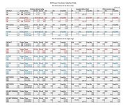
For the Q14/Q15 what about tibis recommendation from the dark side of mouser 🙂 IXFK220N20X3 and IXTK120P20T
For the Q14/Q15 what about tibis recommendation from the dark side of mouser 🙂 IXFK220N20X3 and IXTK120P20T
When you are @ clipping the source of the IXTQ52P10P is @ +50V when the output is most positive and the drain is @ -50V
Greuueueuu !!!!
Difficult to master 50V in practice with a toroid unless you work towards a safe standard 42V or use a regulated power supply.
Not so easy to replace this FQA36P15 not in stock.
I would still do the test but at 48V.
Yes I see that now.Ciss in nF for IXFK220N20X3 and IXTK120P20T.
What about the requirements for Q5 and Q6+
Kind Regards
Dont know the real value but 2GHz works on the prototype. Better to adjust R7/R8 to ovoid oscillation at clip with the Toshiba.
A new P-Channel candidate for Q16. I missed that one.
IXTQ26P20P
https://www.mouser.fr/ProductDetail/747-IXTQ26P20P
IXTQ26P20P
https://www.mouser.fr/ProductDetail/747-IXTQ26P20P
Attachments

I think I would prefer a little higher Ciss with higher Gfs and lower Rds on as in the 36p20p. And it is available now although in TO220 house and will be in stock late August in massive numbers in the TO247 version
Only few 26p20p and the lead time is 40 weeks.
Only few 26p20p and the lead time is 40 weeks.

Hello,
Good news.
Could you do a scope test like this:
20KHz square with 176mVrms at input (for 1.2V sensibility) or something else but around 2Vrms at output?
In use, the TO220 will probably heat up too much (not if the amp is idle).
Stef.
Good news.
Could you do a scope test like this:
20KHz square with 176mVrms at input (for 1.2V sensibility) or something else but around 2Vrms at output?
In use, the TO220 will probably heat up too much (not if the amp is idle).
Stef.
Hello,
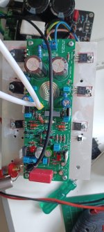
I have tested with the FQA46N15 in Q14 and the IXTQ52P10P and IXTH48P20P in Q15.
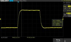
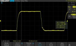
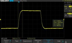
The overshoot problem on the square signal seems to come from gate stopper resistors that are too high in R14 and R15.
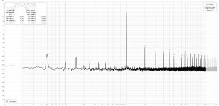
If I take 330R as a value for R14/R15 as on the original circuit, I get a square signal with an overshoot at the output of the square signal. If I start from a base of 100R for R14/R15, the overshoot problem disappears. Under REW the measurement results seem correct after this correction of R14/R15.
330R works with the FQA46N15/FQA36P15 pair but produces an overshoot more or less important with all the other transistors tested (P or N channel).
I have put several screenshots for the FQA46N15 / IXTQ52P10P to show you. The name of the test is in the file name. If I replace the IXTQ52P10P in Q15 with an IXTH48P20P, the behavior is the same.
After lowering R14/R15, it doesn't seem like the Q17 is oscillating but I've only tested it at 1W for the moment.
If you have any comments on this issue and how to resolve it, I'm interested.
Stef.
First screen shot is the original Q17 circuit with FQA46N15 / FQA36P15. Others are FQA46N15 / IXTQ52P10P.
I have tested with the FQA46N15 in Q14 and the IXTQ52P10P and IXTH48P20P in Q15.
The overshoot problem on the square signal seems to come from gate stopper resistors that are too high in R14 and R15.
If I take 330R as a value for R14/R15 as on the original circuit, I get a square signal with an overshoot at the output of the square signal. If I start from a base of 100R for R14/R15, the overshoot problem disappears. Under REW the measurement results seem correct after this correction of R14/R15.
330R works with the FQA46N15/FQA36P15 pair but produces an overshoot more or less important with all the other transistors tested (P or N channel).
I have put several screenshots for the FQA46N15 / IXTQ52P10P to show you. The name of the test is in the file name. If I replace the IXTQ52P10P in Q15 with an IXTH48P20P, the behavior is the same.
After lowering R14/R15, it doesn't seem like the Q17 is oscillating but I've only tested it at 1W for the moment.
If you have any comments on this issue and how to resolve it, I'm interested.
Stef.
First screen shot is the original Q17 circuit with FQA46N15 / FQA36P15. Others are FQA46N15 / IXTQ52P10P.
Attachments
-
 Q17-Mini-3.0_spectrum_1W_R14=110R_R15=100R.jpg402.5 KB · Views: 63
 -
 Q17-FQA46N15-IXTQ52P10P-20KHz-48v-R14_R15=100.jpg43.5 KB · Views: 72
 -
 Q17-FQA46N15-IXTQ52P10P-20KHz-48v-R14_R15=220.jpg43 KB · Views: 68
 -
 Q17-FQA46N15-IXTQ52P10P-20KHz-48v-R14_R15=330.jpg48.8 KB · Views: 64
 -
 Q17-FQA46N15-FQA36P15-20KHz-50v-R14=340_R15=330.jpg47.1 KB · Views: 65
 -
 low_R14_R15.png53.7 KB · Views: 68
 -
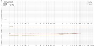 Q17-Mini-3.0_sweep_1W_R14=110R_R15=100R.jpg372.2 KB · Views: 72

- Home
- Amplifiers
- Solid State
- Q17 - an audiophile approach to perfect sound