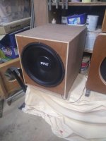
I have a pair of 15" Pyle PPA 15s from a previous OB project that I'm having a hard time moving on.
Was wondering if I can actually integrate them as an OB sub alongside my current Pensils. I'm keen to keep the smallest footprint possible, and wondered if a SLOB might work, with drivers mounted face to face.
Can anyone advise the relevant t/s or other considerations for this type of design?
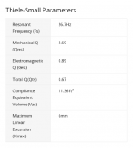
Basic parameters attached.
Was wondering if I can actually integrate them as an OB sub alongside my current Pensils. I'm keen to keep the smallest footprint possible, and wondered if a SLOB might work, with drivers mounted face to face.
Can anyone advise the relevant t/s or other considerations for this type of design?
Basic parameters attached.
Attachments
To answer my own post - I decided that it was finally time to learn Hornresp.
I modelled a SLOB using the PYLE driver, and it wasn't a great looking response - probably fairly typical for OB but it would need to be crossed over lower than I wanted to be usable.
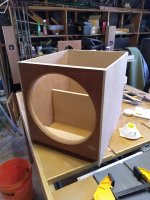
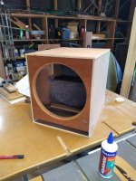
After a bit more experimenting in Hornresp, I ended up modelling the smallest possible MLTL I could. Unfortunately the qts/small box was making it hard to develop a low end response without a significant peak. I did however start to have some success by moving the driver close to the port end, which seemed to smooth things up a lot, along with some generous stuffing.
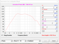
With a couple hours to spare and some scrap timber I put together a test box based on the HR model. I put a divider in the middle to in theory act as a folded MLTL. I had time to take one FR measurement at around 40cm (so includes some 'garage' effects), but it was surprisingly consistent with the modelled response. Anyway, gave me a little more confidence to move onto the next half-baked idea🙂.
I modelled a SLOB using the PYLE driver, and it wasn't a great looking response - probably fairly typical for OB but it would need to be crossed over lower than I wanted to be usable.
After a bit more experimenting in Hornresp, I ended up modelling the smallest possible MLTL I could. Unfortunately the qts/small box was making it hard to develop a low end response without a significant peak. I did however start to have some success by moving the driver close to the port end, which seemed to smooth things up a lot, along with some generous stuffing.
With a couple hours to spare and some scrap timber I put together a test box based on the HR model. I put a divider in the middle to in theory act as a folded MLTL. I had time to take one FR measurement at around 40cm (so includes some 'garage' effects), but it was surprisingly consistent with the modelled response. Anyway, gave me a little more confidence to move onto the next half-baked idea🙂.
Attachments

Hmm, just now seen this and have asked the mods to maybe move it to 'subwoofers' where it seems to be more appropriate.
Regardless, when there's no response plot and especially if there's no inductance spec [Le] to plot its HF response above its upper mass corner [Fhm], then all the BW we can count on is what the T/S specs predicts up to it where it peters out:
Fhm = 2*Fs/Qts'
Qts': 2*Fs/Fhm
[Qts']: [Qts] + any added series resistance [Rs]: Calculate new Qts with Series Resistor
[Rs] = 0.5 ohm minimum for wiring, so may be higher if a super small gauge is used as a series resistor plus any added resistance from an XO/whatever.
At first I thought no, it's about integrating but then yes, it's about building. We can always change our mind later.to maybe move it to 'subwoofers'
 Thread moved.