A good PWM modulation is the first step of class d journey. So i decided to start collect and share PWM modulation circuits under this post.
PWM modulation cause conversion error or Quantization error.
Measure and compare different topologies lighten us to find out which one is better.
I did some but i do not know is it possible to identify error with simulation?
Because it is cheaper way to do so.
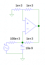
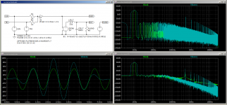
I add a sample self oscilating circuit in LTSpice XVII simulation(pls see atacchements), i am able to get square wave form from sinus wave but squares are seems deformed a little bit. is this the error?
How we can compare 2 different circuit. If it is not possible to do it with simulation i will probably build all topology proposals and compare them.
So for this real life comparison which equipments (signal generator, oscilator....) i need to know the procedure step by step.
PWM modulation cause conversion error or Quantization error.
Measure and compare different topologies lighten us to find out which one is better.
I did some but i do not know is it possible to identify error with simulation?
Because it is cheaper way to do so.
I add a sample self oscilating circuit in LTSpice XVII simulation(pls see atacchements), i am able to get square wave form from sinus wave but squares are seems deformed a little bit. is this the error?
How we can compare 2 different circuit. If it is not possible to do it with simulation i will probably build all topology proposals and compare them.
So for this real life comparison which equipments (signal generator, oscilator....) i need to know the procedure step by step.
Attachments
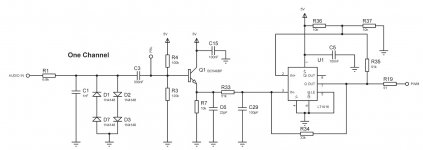
I add a sample self oscilating circuit in LTSpice XVII simulation(pls see atacchements), i am able to get square wave form from sinus wave but squares are seems deformed a little bit. is this the error?
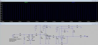
It looks to me like your simulation time steps are much too large to see accurately what the waveform looks like.
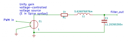
Besides using a smaller maximum step size, in order to prevent aliasing artefacts, you could add an ideal LRC low-pass filter to the circuit, put the modulator's output signal into the filter (buffered by an ideal controlled source to prevent loading effects) and take the DFT of the low-pass filter's output.
It looks to me like your simulation time steps are much too large to see accurately what the waveform looks like.
Besides using a smaller maximum step size, in order to prevent aliasing artefacts, you could add an ideal LRC low-pass filter to the circuit, put the modulator's output signal into the filter (buffered by an ideal controlled source to prevent loading effects) and take the DFT of the low-pass filter's output.
could you please modify and make an example on the first post simulation file inside zip file so we can understand?
Thanks in advance
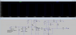
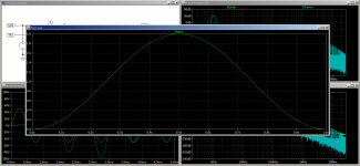
What I meant was to change .tran 0 10m 0 1u into .tran 1n 10m 0 1n or even .tran 100p 10m 0 100p to see the edges better. It can lead to quite long data files, though. You may also have to switch off the waveform compression that LTSpice does by default.
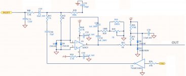
To see whether the PWM circuit works at all, it is handy to put a low-pass filter in the circuit so you can see what your PWM signal would look like after filtering. The attachment is a sketch of a simple second-order Butterworth low-pass at 20 kHz.
If you want to accurately simulate the distortion, you will probably have to take small time steps, switch off waveform compression, look at the low-pass filter output rather than the direct modulator output, skip the first cycle or two, apply a Hann window and then do a discrete Fourier transform. I'm not sure if there are any convenient ways to apply a Hann window in LTSpice, though. I simulate a lot, but not often in LTSpice.
Attachments
Last edited:
Distortion measurements with LTSPICE | Audio Perfection
As long as you match the time of your analysis to an integer number of the frequency of interest you do not need to use windowing. 1KHz... use a multiple of 1mS.
Give your circuit time to settle before starting the analysis.
Specify the UIC directive.
...
As long as you match the time of your analysis to an integer number of the frequency of interest you do not need to use windowing. 1KHz... use a multiple of 1mS.
Give your circuit time to settle before starting the analysis.
Specify the UIC directive.
...
Attachments
That's just the problem: when the ratio between the signal frequency and the PWM clock frequency is irrational and/or not accurately known, you can't choose an integer multiple of both the signal period and the PWM clock period - which means you have to resort to windowing with the associated complications.
Last edited:
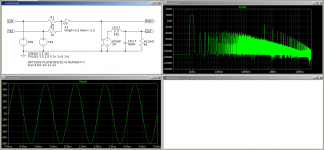
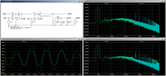
Looking at your latest spectrum plot, I see that all harmonic distortion components are totally obscured by the DFT noise floor, what I think you call the baseline. So if you are interested in the distortion, how are you going to find out what it is? All you can say now is that the harmonics can't be much stronger than -90 dBc, as otherwise they would have stuck out.
If I understand it correctly, you do a 6 ms simulation and skip the first 1 ms. In that case, you could apply a Hann window by adding a behavioural source with value V(out)*(1-cos(2*pi*(time-0.001)/0.005)).
If I understand it correctly, you do a 6 ms simulation and skip the first 1 ms. In that case, you could apply a Hann window by adding a behavioural source with value V(out)*(1-cos(2*pi*(time-0.001)/0.005)).
LTSpice includes a Hann Window as a choice in the FFT menu. Using it or your method does not have much effect on the final results. Maybe I am driving things wrong.
Attachments
It helps above 200 kHz, but that is not what you were interested in, of course. Does further reducing the maximum timestep do anything, or choosing a print timestep such that you have a power of two points for the DFT?
LTSpice defaults to power of 2 for the number of points in the DFT/FFT. At some point reducing the minimum timestep provides no apparent gains in as much as a .FOUR statement does produce lower THD figures down to about 500ps but not noticeably better beyond. I think we're kind of stuck with what it is. The noise floor always seems to correlate with the peak distortion product at any specific frequency.
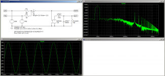
If I include an error amplifier, integrator, then the noise floor gets blown off anyway. Ultimately I think it is one of those things where you have to treat results with a degree of caution or otherwise interpret them.
If I include an error amplifier, integrator, then the noise floor gets blown off anyway. Ultimately I think it is one of those things where you have to treat results with a degree of caution or otherwise interpret them.
Attachments
I'm really more used to Spectre RF and Cadence than to LTSpice, and to sigma-delta modulators and RF circuits than to analogue pulse width modulators, so I don't know to what extent what I'm about to write is applicable, but for what it's worth:
In order to get a nice and clean spectrum out of a transient run followed by a DFT, I usually have to do this:
1. Use tight convergence tolerance settings, particularly reltol.
2. Give the circuit plenty of time to settle - as you have done, so that should be OK.
3. Use an ideal low-pass filter with a cut-off frequency far below the reciprocal of the DFT time step to minimize aliasing. You have a low-pass filter, but how much has it rolled of at the Nyquist frequency 1/(2*DFT time step)?
4. Do the DFT over an integer number of periods of all relevant signals if possible, if not use a Hann window. Windowing also helps to reduce the effect of imperfect settling, by the way. Use at least two periods of the lowest frequency of interest without window or four with a Hann window.
5. Force Spectre to calculate exactly at the time points needed by the DFT using the strobeperiod parameter. I don't know what LTSpice's equivalent is (I would guess the first argument of the .tran statement, but that is just a guess). As the Cadence DFT only works with numbers of points that are powers of two, this means that strobeperiod usually needs to get some funny value with lots of decimals.
6. In LTSpice you have to switch off waveform compression (Spectre has no waveform compression, thank goodness), as you have done with .options plotwinsize=0.
Regarding 3., looking at your plots, I guess you use a 262144 point DFT over 5 ms, resulting in a 19.073486328125 ns DFT time step and a 26.2144 MHz Nyquist frequency. Your filter is approximately second-order Butterworth at 41148 Hz, giving a suppression of 112.17 dB at the Nyquist frequency. That sound good, as far as I can tell.
Is there any way you can tighten reltol or force LTSpice to write data for all integer multiples of 19.073486328125 ns? (You then also have to change the start and end times of the DFT to exact multiples of 19.073486328125 ns.)
Is there any way you can tighten reltol or force LTSpice to write data for all integer multiples of 19.073486328125 ns? (You then also have to change the start and end times of the DFT to exact multiples of 19.073486328125 ns.)
Apparently you can set reltol using .options reltol=1E-5 (or whatever value you want), see Convergence problems? - LTwiki-Wiki for LTspice Too low a reltol may lead to divergence, though. Pity that there is no strobeperiod.
Sorry. I meant I'm not going to try. When it takes 12 decimals to do something I ask whether or not the end goal is worth the effort. I am happy to accept the results I see and use them on a comparative basis.
Here is another one from infineon
potstip where did you get this modulator? I can't figure it out. I think something important was cropped.
- Home
- Amplifiers
- Class D
- PWM modulation