Ok, I see that it's a mangled piece of the old IRAUDAMP* scheme. Thanks.. It'd still be interesting to see the rest of it. I can't find the original drawing.
Last edited:

What I meant was to change .tran 0 10m 0 1u into .tran 1n 10m 0 1n or even .tran 100p 10m 0 100p to see the edges better. It can lead to quite long data files, though. You may also have to switch off the waveform compression that LTSpice does by default.
To see whether the PWM circuit works at all, it is handy to put a low-pass filter in the circuit so you can see what your PWM signal would look like after filtering. The attachment is a sketch of a simple second-order Butterworth low-pass at 20 kHz.
If you want to accurately simulate the distortion, you will probably have to take small time steps, switch off waveform compression, look at the low-pass filter output rather than the direct modulator output, skip the first cycle or two, apply a Hann window and then do a discrete Fourier transform. I'm not sure if there are any convenient ways to apply a Hann window in LTSpice, though. I simulate a lot, but not often in LTSpice.
filter out gave me 0 volt on output.
Attachments
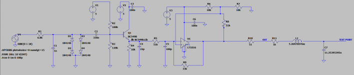
Could you post your schematic in a format that can be read without LTSpice?
Attachments
Last edited: