Before begining the circuit, I don't know if some transistor need heat sink ???
The DC at the output will be something like 410V, and all the zener make 363V... and after that, I will use 1 regulator drop by channel, so I drop from 363v to 330V...
I don't know how much the preamp schematic draw???
Maybe the 3 transistors to drop the voltage to 363V need to have heat sink ??
Please help me!
I'm talking about the PV-12 preamplifier
Hi arold19,
Since it isn't sitting on my bench in front of me, I can't remember enough detail to give you an answer. I am thinking yes.
-Chris
Normally the pass transistor has a heat sink and insulator so the heat sink is not at full supply voltage.Maybe the 3 transistors to drop the voltage to 363V need to have heat sink ??
Since it isn't sitting on my bench in front of me, I can't remember enough detail to give you an answer. I am thinking yes.
-Chris
What do you mean by ¨PASS¨ If you look to the schematic, there a MPSU60, MPSU10 and MJE-340.
Thank you !
Thank you !
Thank you, but do you think the MJE340 to drop the voltage from 363V to 330V need heat sink, it is not a lot of voltage...
Also, remember that my two channel are isolate...
Thank!!
Also, remember that my two channel are isolate...
Thank!!
Complicated regulators
Perhaps I'm late, but I'd like to make a brief mention about complex power supply circuits. Output impedance of a power supply vs. frequency is probably more important than sheer voltage regulation.
The very high capacitance of electrolytics make them seem very attractive at low frequencies, but these frequencies are also where feedback in power suplies is most effective. Trying to "fix" the higher complex impedance of electrolytics at high frequencies is much harder than using film capacitors and then fixing the poorer low frequency regulation with more gain or feedback.
Take a long hard look at the various John Curl power supply designs that appear at several places in this forum. It is arguable that he is the best there is at pre-amp design.
For me it helps to visualize an electrolytic as a power storage device instead of a filter.
Hi hermanv,
The shocking truth is that just as the output impedance goes up with frequency in a series pass regulator, the same is true of a shunt design. The shunt simply has some capacitance to ground instead of to the regulated line. In either case, you have capacitance "through" the pass device and the active regulator circuitry will have similar problems as the frequency increases.
It takes good design practice with either type to get good results. It also helps if your circuit isn't a straight class A type as the supply impunity is low (talking about SS types mostly).
I personally don't see many regulator designs where the bypass caps are used as a main source of energy. They are sized small so they can respond to transients. Of course there is no end to poorly engineered power supplies.
-Chris
Good short term supply voltage regulation from series regulators comes practically free. You tend to see drift, but that should be ignored in favor of a low high frequency impedance. You will often find film caps used to bypass electrolytic capacitors or to simply filter things like a zener stack. Using film caps before and after a series pass element will go a long way to reducing the high frequency impedance.Perhaps I'm late, but I'd like to make a brief mention about complex power supply circuits. Output impedance of a power supply vs. frequency is probably more important than sheer voltage regulation.
The shocking truth is that just as the output impedance goes up with frequency in a series pass regulator, the same is true of a shunt design. The shunt simply has some capacitance to ground instead of to the regulated line. In either case, you have capacitance "through" the pass device and the active regulator circuitry will have similar problems as the frequency increases.
It takes good design practice with either type to get good results. It also helps if your circuit isn't a straight class A type as the supply impunity is low (talking about SS types mostly).
I personally don't see many regulator designs where the bypass caps are used as a main source of energy. They are sized small so they can respond to transients. Of course there is no end to poorly engineered power supplies.
-Chris
Re: Complicated regulators
Hi, hermanv,
Conrad Johnson's regulator is very interesting. It is an open loop circuit like linear stage.
I do some tries with various LM317 configurations. Some of then sounds good and other very poor. Many designers only speak about power supply PSSR, few speak about sounding. With same component you can obtain the better as the worse!
LM317, understanding and listening
Like for cooking. Start to follow the complete recipe. After you can do your own changes.
Eric
Hi, hermanv,
Have you got a link to one of these power supply? I search for it, but don't find. Perhaps it is the 'super regulator'? (standard regulator with girator)hermanv said:Take a long hard look at the various John Curl power supply designs that appear at several places in this forum. It is arguable that he is the best there is at pre-amp design.
Conrad Johnson's regulator is very interesting. It is an open loop circuit like linear stage.
I do some tries with various LM317 configurations. Some of then sounds good and other very poor. Many designers only speak about power supply PSSR, few speak about sounding. With same component you can obtain the better as the worse!
LM317, understanding and listening
Like for cooking. Start to follow the complete recipe. After you can do your own changes.
Eric
Re: Re: Complicated regulators
A darlington follower is very interesting?
Eric Juaneda said:
Conrad Johnson's regulator is very interesting. It is an open loop circuit like linear stage.
A darlington follower is very interesting?
Re: Re: Complicated regulators
If memory serves (forgive me John I have no intention of putting words in your mouth) John tends to treat regulation, ripple and impedance as seperate issues that sometimes can be better controlled with multiple circuits each designed to optimize a solution for one aspect of a power source.
All of the three terminal regulators seems to produce a certain amount of hash (extremely high gain, extremely high amounts of feedback), post regulator RC or LC filters seem like a good idea, even if you give up some sheer voltage stability.
Remember that for almost all amplifier circuits the regulator or at least the regulator output filter appears in series with the output signal (go ahead, trace the full signal current loop from output driver through the load and back to the driver and you will probably find the regulator in series with the path). Because of this, the regulator characteristics are most important if you want the last word in sound quality.
Sorry, I don't recall the exact thread(s). Maybe a search for user "john curl", or "Blowtorch" (pre-amplifier).Eric Juaneda said:Hi, hermanv,
Have you got a link to one of these power supply? I search for it, but don't find. Perhaps it is the 'super regulator'? (standard regulator with girator)Eric
If memory serves (forgive me John I have no intention of putting words in your mouth) John tends to treat regulation, ripple and impedance as seperate issues that sometimes can be better controlled with multiple circuits each designed to optimize a solution for one aspect of a power source.
All of the three terminal regulators seems to produce a certain amount of hash (extremely high gain, extremely high amounts of feedback), post regulator RC or LC filters seem like a good idea, even if you give up some sheer voltage stability.
Remember that for almost all amplifier circuits the regulator or at least the regulator output filter appears in series with the output signal (go ahead, trace the full signal current loop from output driver through the load and back to the driver and you will probably find the regulator in series with the path). Because of this, the regulator characteristics are most important if you want the last word in sound quality.
Hello, my PV12 is almost finish but I have questions for you !
-I use TIP49 and MJE5731 to replace the MPSU10-60, this transistor are more powerful but the brandwidth is a lot difference.... do you think it will change anything in the power supply or in the sound??
-I use a star ground but I don’t know how to wire the inputs and output connector???
I have only 2 input... I think I have to ¨join¨ the left input togetter, the right input togetter and join each channel to the star ground....For the output, I have to use a ground near the tube?? I am realy not sure how to ground the RCA connector ????? Also, the pot, I have to ground it near the tube??
I will put the power on in a couple of day maybe... with a variac, I hope it gonna work !!!!
-Also, do you know what is the PV12 Conrad Johnson 12AU7 original tube??? Now, I have 2 Electro Harmonix
I’m waiting for your answer, thank you for your help !
For a star grounding scheme the input and output RCA jacks must be insulated from the chassis. Then a separate ground wire for each input, each channel and each output is connected to the star ground point, 4 ground wires total for 2 channel.
I bought replacement tubes for my PV 12 from Gold Aero (now out of business I think). I also bought replacements from C-J. The two were identical except Gold Aero wanted half the money. I found the Gold Aero reference from Dick Olshers Hi-Fi pages, Black Dahlia. They were an East German tube.
I sold my PV 12 so I can't go look at the tubes, but in general many tube fans list listening test results, I went for smooth, and the brands seemed mostly to agree with the tests of vacuum tube fans.
Yes it will change, because each device has its how sound. I don't think this transistors will be less than original one.arold19 said:-I use TIP49 and MJE5731 to replace the MPSU10-60, this transistor are more powerful but the bandwidth is a lot difference.... do you think it will change anything in the power supply or in the sound?
I just finish a transistor preamplifier with similar power supply (two serial open loop regulator). It sounds very nice.
I remember theses tubes sounded very well.hermanv said:...I bought replacement tubes for my PV 12 from Gold Aero (now out of business I think)...
Eric
Grounding is a never ending problem. After reading many articles about grounding and earthing, I perform personal tests. Today, I think that internal wiring and grounding is as important as schematic itself.arold19 said:-I use a star ground but I don’t know how to wire the inputs and output connector???
I have only 2 input... I think I have to ¨join¨ the left input together, the right input together and join each channel to the star ground....For the output, I have to use a ground near the tube?? I am really not sure how to ground the RCA connector ????? Also, the pot, I have to ground it near the tube??
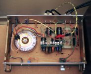
I join picture about my better grounding test. As you can see, I use multiple path ground and multiple path to safety earth (in green).
This strange configuration certainly hurt many people. I will soon write article about it. You can easily compare different grounding by listening test.
Eric
Attachments
I think I have a problem with my power supply !!!
Today, I put the power on only on the first section of the power supply, here is the result. I have 450V at the output of the ¨rectifier¨, the transformer is a 300vAC... I have no load at the output...
The problem is: I have 360V at the Base of the MJE340, this is perfect, and I have 345V at the Emitter... I think the MJE340 is suppose to drop the voltage to about 359V.... Do you think I have a problem or not??
Thank you !
With a Darlington connected emitter follower, leakage from the first transistor can drive the second transistor to a higher than expected output.
When you measure the base voltage the current drawn by the meter although quite low can absorb the leakage, lowering the volage to the expected reading. For test purposes, put a 270K or 470K to ground on the base of the second transistor in the Darlington pair. This resistor will absorb any leakage, now measure again.
If this is the problem, it will probably disappear under load. Also if memoryi serves, the MJE family used a non-common pin-out arrangement, make sure your collector/base/emitter connections are correct.
Your sketch does not show a star ground. Every ground in the circuit should have one wire to a common "star", no other grounds are interconnected any other way
Thank you very much Hermanv, you're right! I maked and error with the pin-out. I puted the Collector insteed of the Emitter.. Now, I have only 0.7V between the Base and the Emitter...
Thank you, I will continu to try the circuit...
Thank you, I will continu to try the circuit...
I have an other problem, with the power supply for the heater of the tubes!
I use the same power supply of the Conrad Johnson Premier Ten for the heater, except, I regulate the voltage at 6.3 insteed of 12.6 because I don't think a have enough voltage... I have 14VDC. The only thing I changed, it is the value of the zener, I use 7.7V insteed 14V...
http://www.analogstereo.com/conrad_johnson_service_manuals.htm
So, I connect the heater in parallele, the (-) on the pin #9 and the (+) on the pins 4 and 5.
Today, I connect only one tube to try, and the voltage doesn't go more than 5.3V, and there is so light coming out of the tube... I tried and other tube and it is the same thing...
Also, without tube, I have 6.3V at the output of the power supply...
Also,I mesure the resistance between pin#9 and 4, and between #9 and 5, I have 7 Ohm for one tube and 18 Ohm for the other, I don't think this is normal.
It is my first tube project, I don't know what to do with this.
Someone can help me ???
Sorry for the post, I think I found the problem...
To have 7.7V, I use one 3V zener and one 4.5V zener, but now, the 3v is working at 2.2V and the 4.5 at 4.3, so I miss about 1.2V...
Why the zener are not so good???
I use an 1N5225B and 1N5230B.
Tomorrow, I will buy some other zener....
Also, it is normal that there no light from the tube at 5.3V. And for the resistance difference between the 2 tubes???
Thank !!!
- Status
- Not open for further replies.
- Home
- Amplifiers
- Tubes / Valves
- PV12 Preamplifier