A couple of days ago I was out walking in the snow and thinking that my class 'A' push-pull amp was about as inefficient a design as you could get. But then I remembered OTL amps! My train of thought chuntered on something like this:
OTLs generally use paralleled output tubes so that each tube seems to see a larger load (amongst other reasons).
Couldn't you get the load to seem larger by driving both ends in phase rather than the opposite phase of a push pull?
If you had two cathode followers (one on each end of the load) and drive them with in-phase signal but attenuate the signal to one (the slave), the other (the master) would effectively see a large load.
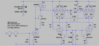
I've modified another spice schematic I was working on to test it (was going to be a CF parafeed) It kind of seems to work but needs tweaking obviously. (Better tube selection, better way of providing unequal drive etc..)
The tubes shown are all ones that were being used in the parafeed project purely due to laziness. As I post this I realize that two SRPPs might be more appropriate than CFs but the principle is the same.
Does anyone know of previous designs like this? I'd like to work it up but if someone can tell me now that "Oh yes, that's the old humperknuckle design from the 60's... fundamentally flawed because of X, Y, and F..." it would save me the bother.
OTLs generally use paralleled output tubes so that each tube seems to see a larger load (amongst other reasons).
Couldn't you get the load to seem larger by driving both ends in phase rather than the opposite phase of a push pull?
If you had two cathode followers (one on each end of the load) and drive them with in-phase signal but attenuate the signal to one (the slave), the other (the master) would effectively see a large load.
I've modified another spice schematic I was working on to test it (was going to be a CF parafeed) It kind of seems to work but needs tweaking obviously. (Better tube selection, better way of providing unequal drive etc..)
The tubes shown are all ones that were being used in the parafeed project purely due to laziness. As I post this I realize that two SRPPs might be more appropriate than CFs but the principle is the same.
Does anyone know of previous designs like this? I'd like to work it up but if someone can tell me now that "Oh yes, that's the old humperknuckle design from the 60's... fundamentally flawed because of X, Y, and F..." it would save me the bother.
Attachments
Err...
Call me daft, but if the signal is IN phase and of the same amplitude, the net output from the load would equal zero...
Call me daft, but if the signal is IN phase and of the same amplitude, the net output from the load would equal zero...
That's vey true so you aren't daft. But the signal to the 'slave' tube is attenuated and therefore not the same amplitude. that's the function of the 72K/400K potential divider between the 5998s.
That is the main problem I'm having though. This divider increases source impedance of the drive signal to the top right tube causing HF roll off and a spike on the leading edge of a square wave test signal. That's why I put the .1nF past the 72K. this isn't ideal though.
Another way would be a 7K/40K divider with a bigger cap, but that reduces the load seen by the preceeding stage. Not good for a Mu follower.
The best way might be to have a divider on the output of the volume control and use the attenuated signal to feed a separate drive stage but then things are getting a bit big, which is what I was hoping to avoid to begin with.
Interesting idea but it's not really going to work at all efficiently.
back to the drawing board and some PL519's.
The correct approach is to use high impedance speakers, say a quad of 15 ohm types is series. So you now have a 60 ohm speaker, with about 3 amps peak available from PL519's, which is 540 Watts peak, 270 RMS, with a peak output voltage of 180 volts. Of course this is seroiusly exceeding permissable anode dissipation but it points the way forward.
Regards
Henry
Or get some of those Philips drivers with the 1000 Ohm voice coil, built especially for this type of amp.
Or get some of those Philips drivers with the 1000 Ohm voice coil, built especially for this type of amp.
Back in the early 1960's, I remember a design by Philips using EL86's for use with an 800 ohm LS, so it isn't new. With modern day adhesives it should be far more reliable.
So we're agreed on the need for HiZ speakers. Do Philips still make the 1000R speakers, and were they any good?
For the sake of practicality and good quality we are back to multiple drivers.
At a london show only a few years back our honoured Tim de P. was demonstrating a speaker he had built which sounded completely fantastic, but has not been seen since or copied. It was a hexagonal column about 70 to 90 cm diameter, and 1.5 meters tall. I'm going from memory on the numbers so can't be absolute.
It had a string of tweeters, maybe eight of them running up the 'front' face and on each adjoining face was a row of mid bass units (6 or 8 inch), possibly six on each side, could have been more.
Anyway the point here is that these drivers could well have been wired up in series and driven by a valve OTL.
If you drive one end of the load with signal X, and the other end with signal X/4 (say), then you get the load effectively receiving 3X/4 - this is a partial bootstrap so it will raise the apparent impedance but at the cost of reducing output power. The load will also be wiggled up and down by a common-mode signal of 5X/8. I can't see the point.
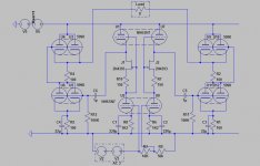
Thanks all for the replies. I've done some further investigation.
Those PL519s sound interesting, I've not seen those before. This was intended to be for my living room though running high efficiency 8ohm drivers (single driver speakers) so 540W would a) destroy my speakers and b) disturb the police. While still in their station. On the other side of town! I was aiming for up to 5W into 8 Ohms.
And if I was worried about efficiency I'd be using sand.
Incidentally it seems odd to say
I think the arrangement does have it's merits. You can use virtually any tube with enough current to drive very low loads.
DF96- You are right about the load recieving only the partial signal that has been amplified, but that is the voltage that has been amplified. Considering two SRPPs at the output- as the voltage rises the current from the master will drive the slave CF more than its own drive signal due to the slave cathodes low impedance and lower tubes high impedance. Effectively it is still push pull regarding current as the slave side sees and inverted loadline (greater than infinate). The more asymmetric the input signal the lower the apparent load / the harder the output stages are pushed so in theory the tubes can be used as efficiently as any other topology.
Your last point about the load seeing common mode AC is also true but I don't know if that would affect anything, the speaker won't play anything common-mode, although you wouldn't be able to ground anything at the output, even with both output caps in place, so that may be an issue.
Those PL519s sound interesting, I've not seen those before. This was intended to be for my living room though running high efficiency 8ohm drivers (single driver speakers) so 540W would a) destroy my speakers and b) disturb the police. While still in their station. On the other side of town! I was aiming for up to 5W into 8 Ohms.
And if I was worried about efficiency I'd be using sand.
Incidentally it seems odd to say
I suppose all those people listening to Futterman variations or circlotrons on their rear loaded lowthers are way off base eh?The correct approach is to use high impedance speakers...
I think the arrangement does have it's merits. You can use virtually any tube with enough current to drive very low loads.
DF96- You are right about the load recieving only the partial signal that has been amplified, but that is the voltage that has been amplified. Considering two SRPPs at the output- as the voltage rises the current from the master will drive the slave CF more than its own drive signal due to the slave cathodes low impedance and lower tubes high impedance. Effectively it is still push pull regarding current as the slave side sees and inverted loadline (greater than infinate). The more asymmetric the input signal the lower the apparent load / the harder the output stages are pushed so in theory the tubes can be used as efficiently as any other topology.
Your last point about the load seeing common mode AC is also true but I don't know if that would affect anything, the speaker won't play anything common-mode, although you wouldn't be able to ground anything at the output, even with both output caps in place, so that may be an issue.
Attachments
The first line of you original thread suggested you wanted something vuagely efficient.
The new circuit looks a bit better than the first, but...
The 5998's in the outputs are rated to run at 100mA with 110 volts across them. I don't have the full spec so not sure at what grid volts.
In this circuit the best you can get is about 400mA peak current, which translates to a peak voltage of 3.2V across your 8 ohm speaker. This is a massive 1.28 watts peak, or 640mW RMS. We're a bit short of the desired 5 Watts.
To get our 640mW, we'd need at least 100 volts across the valve delivering the current, which would mean something like a 400 volt supply rail. With a standing current of c.100mA for each valve, the supply would have to deliver 400 volts at 400mA, thats 160 watts in for .64 of a watt out, worse than 0.5% efficient.
Add to that each valve is dissipating 20 watts, when 11 is max then they will have a short life.
So back to the drawing board.
The people listening with Futtermans and the like, are all using PL518's, so have a peak current available of around 3 Amps. Across an 8 ohm load this is 24 Volts peak, and 72 Watts peak, 36W RMS.
Of course to achieve this at least 200 watts is drawn off the power supply, again vastly exceeding max permissable anode dissipation, which in practice means something like a practical limit of 10 to 15 watts output power, which is what we find in practice.
Here we are assuming using two valves in the output stage.
Bootstrapping is normally used when you want a component to 'disappear'.
"Efficient" is not a word I would use about two Class A outputs working against each other.
Maybe I have missed something, but to me it looks daft!
"Efficient" is not a word I would use about two Class A outputs working against each other.
Maybe I have missed something, but to me it looks daft!
OK, OK, I submit! Even LTspice is against me. 🙁 It keeps locking up at 13us and saying 'Timestep too short' so i can't even test the circuit. I wasn't planning on using 5998s to make it. I was just trying to see if an unsuitable tube could be used to drive 8 Ohms. I would think that a few 6C33C would be a much better option. I honestly thought that most OTLs were based on 6C33C or 6AS7/6080 valves. As I said, I've never heard of these PL519 but they seem another good choice. My point about the earlier comment was that using high impedance loudspeakers, while obviously a good option, is no more 'correct' than finding ways for valves to drive low loads.
The whole idea sort of started half as a joke, like I said- I thought I had the worst efficiency amp, but then realised I could build a worse one...😎
And you can add 60W of heater power into that equation, and that's still only the output stage...
The whole idea sort of started half as a joke, like I said- I thought I had the worst efficiency amp, but then realised I could build a worse one...😎
And you can add 60W of heater power into that equation, and that's still only the output stage...
We all have daft ideas from time to time. Sometimes we notice before telling anyone else, sometimes we have to be told by them it is daft and eventually agree.
A few of us persist with daft ideas and manage to convince other people to spend their money on them. The big mystery then is: do the people selling daft ideas know they are daft (but hope we haven't noticed), or do they still believe them?
A few of us persist with daft ideas and manage to convince other people to spend their money on them. The big mystery then is: do the people selling daft ideas know they are daft (but hope we haven't noticed), or do they still believe them?
I've been using OTLs for the last 35 years.The people listening with Futtermans and the like, are all using PL518's, so have a peak current available of around 3 Amps. Across an 8 ohm load this is 24 Volts peak, and 72 Watts peak, 36W RMS.
Of course to achieve this at least 200 watts is drawn off the power supply, again vastly exceeding max permissable anode dissipation, which in practice means something like a practical limit of 10 to 15 watts output power, which is what we find in practice.
Here we are assuming using two valves in the output stage.
I've yet to use PL518s- too inefficient. That's a really high power tube but its hard to make power with them in an OTL. I use 6AS7Gs. Two of them with a much simpler circuit will get you more than 5 watts into 8 ohms. In a Circlotron.
If you used two 6C33s you would be good for 15 watts and if you used two 7241s you would be good for 50-60 watts in class A. I've done it. I use the 6AS7G as the socket requirements are easier and the tube is easier to find and usually inexpensive, yet has good linearity.
The project is quite feasable but the schematic rendered while functional, is otherwise very inefficient.
Checkout
http://www.diyaudio.com/forums/tubes-valves/161112-what-tubes-tube-amp.html
The 6AS7G (6080) is rated to run at 125mA, that means it's happy with peaks up to 250mA. All well made valves have a fair bit of surplus built in to cope with ageing, so with the sails up and a good following wind you might just get 400mA peak. With both sections strapped together that gives you 800mA peak. Across an 8 ohm load that translates to 5 Watts peak. It's still only 2.5 Watts RMS.
Perhaps Atmasphere you'd like to share you circuit with the rest of us.
Regards
Henry
Perhaps Atmasphere you'd like to share you circuit with the rest of us.
Regards
Henry
The circuit is in the link I provided. Its on the 3rd page. 5W into 8 ohms with a pair of 6AS7Gs is no worries. At that impedance though such an amplifier will not be class A.The 6AS7G (6080) is rated to run at 125mA, that means it's happy with peaks up to 250mA. All well made valves have a fair bit of surplus built in to cope with ageing, so with the sails up and a good following wind you might just get 400mA peak. With both sections strapped together that gives you 800mA peak. Across an 8 ohm load that translates to 5 Watts peak. It's still only 2.5 Watts RMS.
Perhaps Atmasphere you'd like to share you circuit with the rest of us.
Regards
Henry
- Status
- Not open for further replies.
- Home
- Amplifiers
- Tubes / Valves
- Push-Push OTL?