Nonsense.
The way I described is the way manufacturers have done it for decades now.
Go look at some vintage schematics of amps, then you'll see.
I'm talking about putting the screen B+ after the RESISTOR - THIRD cap, which should be increased to 47uf.
The way I described is the way manufacturers have done it for decades now.
Go look at some vintage schematics of amps, then you'll see.
I'm talking about putting the screen B+ after the RESISTOR - THIRD cap, which should be increased to 47uf.
Attachments
Last edited:
Ah, now you shifted a cap 😀
Many output tubes like to have a (much?) lower voltage on the screen, what you see in those amps is a cheap and not so good way to get that.
The EL84 can have the screen at the same voltage as the anode, lowering the screen results in less anode current and less output power.And a not so stable screen gives more distortion.
Mona

That's for regulation (then you should invert the resistor/Ne-tube place).Here it is to reduce the screen voltage (6L6 don't like high screen voltage) without loosing the low supply impedance.
Mona
Mona
Then please explain to me something.Ah, now you shifted a cap 😀
Many output tubes like to have a (much?) lower voltage on the screen, what you see in those amps is a cheap and not so good way to get that.
The EL84 can have the screen at the same voltage as the anode, lowering the screen results in less anode current and less output power.And a not so stable screen gives more distortion.
Mona
You say: "lowering the screen results in less anode current and less output power"
Where do you get your findings?
However, if the EL84's are wired "triode" mode with the screens directly at the same point as the plates (300V) those tubes only produce a small fraction of the power as if they were wired for pentode operation.
Class A/B operation: @300V
Pentode power output = 17 watts
Triode power output = 5.2 watts
That's because in pentode mode, the screen has B+ on it all the time. In triode mode, the screen is at the voltage of the plate, not B+.
Triode mode = voltage controlled resistance.
Pentode mode = voltage controlled current source.
And most datasheets show plate curves at different screen voltages.
Here is one for the 6L6GC.
Triode mode = voltage controlled resistance.
Pentode mode = voltage controlled current source.
And most datasheets show plate curves at different screen voltages.
Here is one for the 6L6GC.
Attachments

Last edited:
Do we have another (happy ?) amateur here ? 😀Then please explain to me something.
You say: "lowering the screen results in less anode current and less output power"
Where do you get your findings?
However, if the EL84's are wired "triode" mode with the screens directly at the same point as the plates (300V) those tubes only produce a small fraction of the power as if they were wired for pentode operation.
Class A/B operation: @300V
Pentode power output = 17 watts
Triode power output = 5.2 watts
Mona
I really don't know. I assume you're being amusing.
As for me, I've been a professionally educated and highly respected servicer for over 45 years now.
I ran several repair shops, sales outlets, and built loads of "custom" equipment over the decades.
As for me, I've been a professionally educated and highly respected servicer for over 45 years now.
I ran several repair shops, sales outlets, and built loads of "custom" equipment over the decades.
Well at my age (77) i don't take everything not that serious any more.The forum is a nice way to stay awake 😎
Probably you have been focussing to much on the commercial side of the job and your electronic scills are a bit rusty.
The remarks about the screen voltage in pentode and triode mode in respect to the anode voltage and the effect on output power don't make sense.
Mona
Probably you have been focussing to much on the commercial side of the job and your electronic scills are a bit rusty.
The remarks about the screen voltage in pentode and triode mode in respect to the anode voltage and the effect on output power don't make sense.
Mona
Trust me, I'm not "rusty", and I'm 66 now and still sharp.
As for the screen voltage pentode/triode, why don't they make sense?
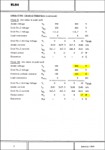
Those statistics were taken directly from the RCA Receiving Tubes master manual - so you're saying that the RCA book is not making sense?
You may have a manual handy, look up the 6BQ5 (EL84) page.
As for the screen voltage pentode/triode, why don't they make sense?
Those statistics were taken directly from the RCA Receiving Tubes master manual - so you're saying that the RCA book is not making sense?
You may have a manual handy, look up the 6BQ5 (EL84) page.
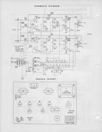
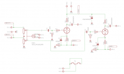
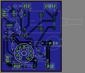
Guys, I don't want to disrupt your conversation, but I did a next small step for me (but probably not a big leap for a mankind 😀 ) and I revised diagram and created a PCB for the preamp.
As my skill in eagle is very basic (but I'm keen to learn!), it would be great if some of you could take a more experienced look at what I created.
Best regards from extreme hot Poland (36C today😱 )
As my skill in eagle is very basic (but I'm keen to learn!), it would be great if some of you could take a more experienced look at what I created.
Best regards from extreme hot Poland (36C today😱 )
Attachments

Just because they don't include screen curves doesn't mean they don't exist.
Go get a bloody tetrode or pentode and make your own. See how well it works with no screen voltage. Zero current or damned close to it. FWIW I have no formal electronics training, have built more than 10 amps that work well, and I'm only 41.
Have a look at this for a refresher maybe? Tubes 201 - How Vacuum Tubes Really Work
"The triode was the first amplifying device to be built, but at radio frequencies it suffers from a grave disadvantage because of the Miller Effect, which gives it a large effective input capacitance in the conventional common-cathode circuit. To avoid this, the tetrode was invented, having a second grid (the screen grid) between the triode grid (called the control grid in multi-grid tubes) and the plate. This grid is connected to a positive voltage close to the plate potential, but grounded to high frequencies through a decoupling capacitor. This results in an electrostatic shield which reduces the effective control grid-plate capacitance to a very low value.
A secondary effect of the screen grid is to reduce dramatically the influence of the plate voltage on the current flow, since the cathode is shielded from the plate by not one but two grids, and their screening effect is multiplied. As a result, the plate curves of a tetrode are very flat, as seen on the right-hand side of Figure 11. This corresponds to a very high value of plate resistance, as compared to a triode.
Some of the current from the cathode goes to the screen grid rather than the plate. The proportion depends on the shielding factor of the screen grid and on the relative potentials of the two electrodes, in much the same way as for a triode operated with a positive grid, and is typically 10-25%."
Last edited:
Same thing here yesterday (not fot from Brussel) now is was "only" 30°C 😉Best regards from extreme hot Poland (36C today😱 )
If that pre is to be used with that power-amp no need for two volume controls and you can skip some capacitors.
The cathode resistor(s) for the EL84 is 270ohm each (better) or 150ohm for the two.
R13 is 470k not 470 😱
Mona
It's not the book but your interpretation is wrong 🙁Those statistics were taken directly from the RCA Receiving Tubes master manual - so you're saying that the RCA book is not making sense ?
Mona
Sorry guys, I did upload a wrong screenshot. May I asked the moderator to change my previous post in order to avoid the mess? A correct screenshot is attached here.
Looks good to me, but C2 only needs to be 47u or so... 470u is overkill 🙂
I build the amp with e88cc, it sound great!
Thank you all for the help.
Another question: is possible to make a headphones output?
Thank you all for the help.
Another question: is possible to make a headphones output?
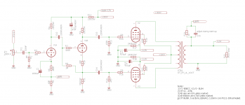
Hi folks,
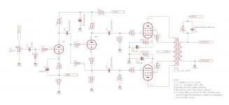
as the autumn started, I had a chance to start-up the amp. Everything worked well, except output power, that seems to be a bit too small 😕 .
I followed the value from the Philips datasheet, Vb=Vg2=300V, Rk 230R (per tube). Measurements showed that cathode voltage is about 11,8V, and the signal is about 14V. Ripples at HV are about 2V. Total capacity in HV power supply seems to be a bit low - around 160uF.
I marked the values at the drawing. Does anyone have an idea of how I can increase output power? I don't really want to go higher with anode voltage, just because my labo autotransformer is already at the of the scale 😀
I know, that in this case, more doesn't mean better (higher distortion etc. 😱 ) but I'm just curious to reach the limit value. In the final solution, I switch the system to UL, what for sure decrease maximum power.
Attachments
- Home
- Amplifiers
- Tubes / Valves
- Push-Pull EL84 amplifier