Thanks for the schematic. Can i bypass the 240ohm cathode resistor and remove Nfb for more gain?
Thanks for the schematic. Can i bypass the 240ohm cathode resistor and remove Nfb for more gain?
You can bypass the 240R but you can't use gNFB in that configuration. My experience says even minimal gNFB makes a pentode sound a lot better.
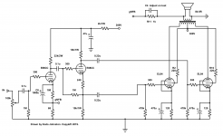
You could split the difference, as shown below.
Attachments
Running pentodes "wide open" results in poor damping factor and a "soggy" (for lack of a better term) sound, it's not really recommended unless your speakers have a very flat impedance curve, as well as very low impedance pentodes. Running even a small amount of feedback will make a huge difference in sound quality and distortion performance.
If you prefer the "no feedback" approach then UL or triode connected is a better choice.
If you prefer the "no feedback" approach then UL or triode connected is a better choice.
You can bypass the 240R but you can't use gNFB in that configuration. My experience says even minimal gNFB makes a pentode sound a lot better.
You could split the difference, as shown below.
I simulate the circuit with spice and see the gain of the preamp is very low, i need full power at 0.5v input and i think this is amp has too less gain...
If you need more gain this one will swing over 100V. 😀
Since the EL84's are "easy to drive" tubes, and only require around 20 volts RMS peak-to-peak in class A/B operation, that schematic you posted would be wildly over-rated.
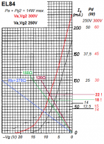
With Vb=300V and Rk=120Ω you wil getting nice red EL84's 😀
Mona
I usually run my EL84's with reasonable bias - 150 ohms paralleled with 47 or 100Uf caps.
Vb around 300V.
With Vb=300V and Rk=120Ω you wil getting nice red EL84's 😀
Mona
Good catch. 120 is usually for when the cathodes share the resistor. All my amps have been fixed bias for years, I guess I wasn't thinking about it.
Make them 240R instead 🙂
Since the EL84's are "easy to drive" tubes, and only require around 20 volts RMS peak-to-peak in class A/B operation, that schematic you posted would be wildly over-rated.
Indeed. It was in fact facetious 🙂 I use it to drive 6P45S triode connected. They need ~220Vp-p swing for full output.
However, without the 12SN7 stage it'd be great, and have enough gain for a bunch of gNFB.
It will use-up your tubes mare quickely.I usually run my EL84's with reasonable bias - 150 ohms paralleled with 47 or 100Uf caps.
Vb around 300V.
Look here,
Mona
Attachments
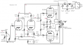
Hello,
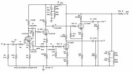
first-time poster here. I reworked a bit kodabmx schematic. Could someone please check if the values of elements are correct? I wonder if I should add resistors between UL and G2. My amp is supposed to be working with a pair of Fostex FE126 in a standard cabinet.
first-time poster here. I reworked a bit kodabmx schematic. Could someone please check if the values of elements are correct? I wonder if I should add resistors between UL and G2. My amp is supposed to be working with a pair of Fostex FE126 in a standard cabinet.
Attachments
1) A 100 ohm resistor in line with the UL is a good safety measure to protect those grids.
2) No need for that 300 ohm on the grid of the phase inverter or input tubes.
3) Reduce the common cathode resister from 240 to 150.
4) Add a 10Uf filter cap after the 22K B+ feed to the input/PI tubes.
2) No need for that 300 ohm on the grid of the phase inverter or input tubes.
3) Reduce the common cathode resister from 240 to 150.
4) Add a 10Uf filter cap after the 22K B+ feed to the input/PI tubes.
1) A 100 ohm resistor in line with the UL is a good safety measure to protect those grids.
2) No need for that 300 ohm on the grid of the phase inverter or input tubes.
3) Reduce the common cathode resister from 240 to 150.
4) Add a 10Uf filter cap after the 22K B+ feed to the input/PI tubes.
1: agreed
2: it's a grid stopper. Stops RF oscillations. It's a 1 cent part. Don't be cheap. Include it.
3: Replace the common cathode resistor with two 240R/470uF caps (one for each tube) for better balance.
4: 47u would be even better IMHO.
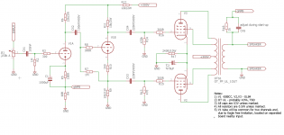
Another alternative, still the ECC82 but with some positive and negative feedback, who needs a 88 😀
Mona
The problem with that schematic is that the B+ feed for the EL84s when in Pentode mode, should be taken from the same B+ (300V) as the input/phase inverter, not directly from the EL84 B+ (315V) supply.
The way it is wired is not Pentode/UL, it is Triode/UL.
Last edited:
That makes no sense to me. Why would you want to run the output tubes through the extra RC filter? Or are you just talking about the screen supply, and not the plate supply?
And to me, the way it's wired it's never in triode mode because the screen either connects to the UL tap or to B+, never to the plate.
And to me, the way it's wired it's never in triode mode because the screen either connects to the UL tap or to B+, never to the plate.
I was stating the screen supply, to clarify things. And the usual, traditional way is to connect the screens to the second PS cap (after the resistor), and I'd change that cap from 10 to 47uf as well.
I don't know who drew up that schematic, but it's certainly an amateur job.
I don't know who drew up that schematic, but it's certainly an amateur job.
The screen is connected to the second cap, the first one is between rectitier and choke 😀
If you put the screen after the resistor you get a less stable screen voltage and a feedback of the output (screen-) current to the driver stage with a risk of motorboating.
Mona
PS. I love to be an "amateur" 😛
If you put the screen after the resistor you get a less stable screen voltage and a feedback of the output (screen-) current to the driver stage with a risk of motorboating.
Mona
PS. I love to be an "amateur" 😛
- Home
- Amplifiers
- Tubes / Valves
- Push-Pull EL84 amplifier