Gentle Folks: Just got back from OTC in Houston (THE trade show for the Oil Patch, that which feeds the family and these indulgences) and have a little time to read and post.
All very informative, thanks! It appears to me that the Menno circuit on Post 17 senses current movement about a level set by the reference, which works great for Class A, and makes use of the diode clamps around the buffer/integrator to force the sampling to be within Class A excursions even when operating at AB. Should work though I would expect some sloppiness is possible as the tube transitions from A to AB until it's deep into AB. I'd love to hear actual performance reports. If satisfactory, great, otherwise I have a paper design which uses a comparator instead of diode clipping for greater precision, independent of signal level.
But as stated on another post in this threas, I have no desire to reinvent the wheel, if the current circuit work well, I'll be the first one to plagiarize and incorporate to my own.
Y'all please publish away with actual first hand testimonials, we'll all benefit!
Rene
Well,
It looks like the Menno circuit is in production so how different is the production version to the circuit we have in the thread?
Tube bias control
Regards
M. Gregg
It looks like the Menno circuit is in production so how different is the production version to the circuit we have in the thread?
Tube bias control
Regards
M. Gregg
The usual way to cope with Class AB is to clip the current monitoring signal at 2 x bias level to balance the fact that it cuts off for part of the cycle. The Menno scheme works in a similar fashion but effectively clips the signal in a much narrower window about the bias point. The commercial offering has 4 of the posted circuit plus power supplies (including the bias supply).
Cheers,
Ian
Cheers,
Ian
Parts are 0805, here is a schematic and layout. Dimensions are like 1.5" x 2"
Thanks for the schematics. Looks like its somewhat different from original Broskie circuit. Can you please explain your mods (apart from replacing FET with high-voltage mosfet)?
There is another mod (made by GeeK) published here:
Modified Broskie Autobias Circuit
Like Broskie circuit, it is published under Copyleft license.
Modified Broskie Autobias Circuit
Like Broskie circuit, it is published under Copyleft license.
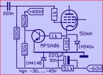
To keep it simple,perhaps like this.Just a suggestion,didn't try it.
Other tube in PP same circuit.Since the Vbe of the transistor is the reference,best glue the two together for the same temperature on both sides.For another baiscurrent change the cathodeR for 0.6V at the desired current.
Mona
Other tube in PP same circuit.Since the Vbe of the transistor is the reference,best glue the two together for the same temperature on both sides.For another baiscurrent change the cathodeR for 0.6V at the desired current.
Mona
Attachments
Microcontroller: Tube Amp Auto Bias & Monitoring
Why not employ a microcontroller for bias monitoring and possible auto adjustment via digital pot?
Why not employ a microcontroller for bias monitoring and possible auto adjustment via digital pot?
The Ketje circuit is simple, I like that, but I don't think it can work in anything but strict Class A. Plus no autobalancing. But, if Class A, and perhaps augmented a bit with an OP AMP driving the MPS06 (for precision, stability and easy adjustability) instead of letting the Vbe be the reference then it will be very nice. If Class AB, the basic idea can still be made to work provided some sort of clamping is utilized so only the current inside the Class A band is perceived. One tube can be bias controlled and the other can be differentially measured with a separate servo circuit. Between the first and second servoes, both absolute bias point and relative balance can be maintained.
Or, if you are good with programming, use greenm01's idea. Depending on level of sophistication of the code, the sampling (making sure only the current immediately above and below Iq is processed), integration, absolute measurement and balancing can all be done. I would suggest one which incorporated ADC channels. Not much resolution is needed, 8 bits ought to be enough. Micro Chips has several, as does Analog. I use both in Gas/Oil drilling guidance systems.
But it will be relatively complex and likely require a good measure of R&D. I would prefer the analog route instead.
Whichever approach is used, it will be wise to limit the authority of the servo, to help prevent runaway situations. And either way, the integration interval must be quite large so only DC error correctons result.
Rene
It is better to get rid of cathode resistors in high-quality amplifiers. Especially if the circuit uses cathode feedbacks with the winding of the transformer. Therefore, it is more promising to receive a feedback signal for bias servo from the anode circuit. A very good solution with a galvanic isolation on an optocoupler is used in amplifiers Audio Research VT-130.
Last edited:
 http://www.4tubes.com/SCHEMATICS/BY-BRAND/Audio-research/VT130_schematic1.gif
- Status
- Not open for further replies.
- Home
- Amplifiers
- Tubes / Valves
- push pull bias servo