Hello,
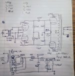
I have in my stash a set of small pushpull output transformers and visually matching power transformers. The OPTs are Z=10k max 10W with screen taps. The power transformers have 270-0-270 VAC 50mA, 5VAC 2A, 6.3VAC 1.5A windings.
I was thinking to build as good a power amplifier as I can, using these and other good components I have in storage. I came up with the idea to do a differential amp using 6N6p as power stage and 6N1p as driver stage. The plan is to use it as a tweeter amplifier in my active Linkwitz Orion speaker system, so it will only handle frequencies above 1500 Hz, I'm thinking the approx 2W max output should be sufficient for dedicated tweeter amplification (?).
It has been a number of years since I built my latest tube amp so please take a look at the schematic and give me your opinions. Is there something that will not work correcty, or can be improved without to much hassle?
Attachments
Looks good. I would make the following changes.
Put 1M across each VR tube to ensure they strike properly...
You could change the coupling caps to 0.01u if you don't need bass.
Go with individual RCs on each output tube cathode for better performance.
Let us know how things go 🙂
Koda
Put 1M across each VR tube to ensure they strike properly...
You could change the coupling caps to 0.01u if you don't need bass.
Go with individual RCs on each output tube cathode for better performance.
Let us know how things go 🙂
Koda
Should do quite well. My suggestions:
Place a 100k resistor in parallel with one of the VR tubes. This will encourage heavy application of starting voltage across the other one, resulting in a successful fire. Then, the other one with the parallel resistor fires second. The idea is to provide sequential firing rather than simultaneous firing. Feeding VR tubes with a CCS works really well as long as you have enough headroom on the raw DC to allow firing.
I have not found the 22k loading resistors to be necessary, YMMV.
Consider (if you have access to measuring equipment) utilizing the Western Electric capacitor (ala Lynn Olson/harmonic balancer) from 'A' to common cathode on the output stage. Personally, I have no problem with the shared cathode resistor; keep the stage as differential as possible. In fact, since you are driving tweeters you could probably get optimal results with a CCS in the cathode as opposed to the 330 ohm resistor. A negative supply would be recommended, however, so you may not want to choose this option.
Or put one CCS on each cathode to ensure DC balance in the OPT. Bypass each with a big (10,000uF) cap or you'll make an eternal silence machine 😀
The CCS can be a simple LM317.
The output stage can't leave class A for very long (brief peaks of AB are possible due to the size of the bypass cap) but you want a tweeter amp so class A would be desirable I think.
The CCS can be a simple LM317.
The output stage can't leave class A for very long (brief peaks of AB are possible due to the size of the bypass cap) but you want a tweeter amp so class A would be desirable I think.
Should do quite well. My suggestions:
Place a 100k resistor in parallel with one of the VR tubes. This will encourage heavy application of starting voltage across the other one, resulting in a successful fire. Then, the other one with the parallel resistor fires second. The idea is to provide sequential firing rather than simultaneous firing. Feeding VR tubes with a CCS works really well as long as you have enough headroom on the raw DC to allow firing.
I have not found the 22k loading resistors to be necessary, YMMV.
Consider (if you have access to measuring equipment) utilizing the Western Electric capacitor (ala Lynn Olson/harmonic balancer) from 'A' to common cathode on the output stage. Personally, I have no problem with the shared cathode resistor; keep the stage as differential as possible. In fact, since you are driving tweeters you could probably get optimal results with a CCS in the cathode as opposed to the 330 ohm resistor. A negative supply would be recommended, however, so you may not want to choose this option.
Thank you for your comments and suggestions!
I had a recent look at Lynn Olson's designs and saw that he uses in addition to the parallell high ohmic resistor you suggest, also a 330R series resistor between the 2 VR tubes. I don't quite understand the purpose for this series resistor?
My builds used mostly design elements from Lynn Olson (also built the Ariel speakers and still use ME2 as a home-cinema center channel speaker) and Gary Pimm. I still have 6 of Gary Pimm's self-bias CCS I made long time ago so will be nice to put them in use!
The 'harmonic balancer' is very interesting, I did some googling and reading about it today and it seems it was originally a resistor with series cap where one adjusted the R to achieve minimum odd order harmonics. Only using the cap seems to be preferred also by Lynn O, to have the arrangement less inluenced by the load reactance as I understand it.
I never tried experimenting with this, although I built an amp similar to the Amity for my electrostatic headphones. I used to have a good card and software for distortion measurement but the card is no longer compatible with modern computers.
In that headphone amp (still use it) I put a CCS under common cathode in both driver and output stages and the amp does indeed sound great as long as not overdriven.
Or put one CCS on each cathode to ensure DC balance in the OPT. Bypass each with a big (10,000uF) cap or you'll make an eternal silence machine 😀
The CCS can be a simple LM317.
The output stage can't leave class A for very long (brief peaks of AB are possible due to the size of the bypass cap) but you want a tweeter amp so class A would be desirable I think.
The eternal silence machine sounds like a interesting project for an artist maybe 😀
So if I understand correctly:
2 separate cathode CCS legs in the output stage would have the advantage of possible perfect cancelling of standing current in the OPT., and the large (and necessary) bypass caps would give a better overload behaviour?
Instead having one shared CCS in the cathode would not need a bypass cap?, but would instead give bad overload characteristic and would probably sound worse anywhere close to max power, am I right?
Most of LL transformer tend to hump at few ten kHz without proper secondary loading.I have not found the 22k loading resistors to be necessary, YMMV..
Must be measuring the frequency response.
I had a recent look at Lynn Olson's designs and saw that he uses in addition to the parallell high ohmic resistor you suggest, also a 330R series resistor between the 2 VR tubes. I don't quite understand the purpose for this series resistor?
I made mine 100 ohms instead of the 330. I use it as a convenient point to measure shunt current. Other than that, I see no real purpose. If anything, series resistance in the shunt path will adversely affect regulation, so keep it small (if you add it at all).
If. If you use one CCS you don't need to bypass it, but the tubes would need closer matching for DC balance. Think of what would happen if you removed one of the tubes? The other one would try to pull twice the normal current. If they aren't matched, one will hog current. Separate CCS insures this is never the case.
Also, I mistyped, 1,000uF is fine on each separate CCS, no need for 10,000uF.
Also, I mistyped, 1,000uF is fine on each separate CCS, no need for 10,000uF.
The eternal silence machine sounds like a interesting project for an artist maybe 😀
So if I understand correctly:
2 separate cathode CCS legs in the output stage would have the advantage of possible perfect cancelling of standing current in the OPT., and the large (and necessary) bypass caps would give a better overload behaviour?
Instead having one shared CCS in the cathode would not need a bypass cap?, but would instead give bad overload characteristic and would probably sound worse anywhere close to max power, am I right?

Nice drawing planet10 🙂
What program do you use?
The VR75 symbol is upside down and the VR125 should be VR105. I think the 1M resistor is not needed as I understand it.
My power transformers are marked LM-47B (don't know if anyone sells those or the OPTs anymore).
As rectifier I will use the EZ81 as I found several of those at home but had only 1 5AR4. The EZ81 seems to have almost the same low voltage drop but needs only 1A heater current
Last edited:
Since you are using current sources as loads in the driver circuit you don't really need the fancy low voltage supply as the tube's operating conditions will be established by the CCS.
I do recommend using cascode sources whether using as a CCS or follower which will have very good PSRR. Just well filtered unregulated DC is all that is required.
Fixed bias or CCS (class A only) on the output stage would be good as well. (Battery bias is a possibility with the 6N6P.)
I do recommend using cascode sources whether using as a CCS or follower which will have very good PSRR. Just well filtered unregulated DC is all that is required.
Fixed bias or CCS (class A only) on the output stage would be good as well. (Battery bias is a possibility with the 6N6P.)
Good point, the regulated supply is unnecessary if using decent CCS as plate loads.
If you are using separate cathode resistors in the output stage then take out the common bond (it is shown as tied together in your drawing).
If you are using separate cathode resistors in the output stage then take out the common bond (it is shown as tied together in your drawing).

The 5AR4 needs a 5V winding, obvoiusly this is just a typo.
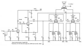
FWIW: This is the 6N6P amp I built in a cake pan a few years ago. It's a nice sounding amp for a super-flea.
The power supply is a 12V - 280V boost converter, and the heaters connect in series for 12V pairs.
FWIW: This is the 6N6P amp I built in a cake pan a few years ago. It's a nice sounding amp for a super-flea.
The power supply is a 12V - 280V boost converter, and the heaters connect in series for 12V pairs.
Attachments
Since you are using current sources as loads in the driver circuit you don't really need the fancy low voltage supply as the tube's operating conditions will be established by the CCS.
I do recommend using cascode sources whether using as a CCS or follower which will have very good PSRR. Just well filtered unregulated DC is all that is required.
Fixed bias or CCS (class A only) on the output stage would be good as well. (Battery bias is a possibility with the 6N6P.)
Hi Kevin, thanks for your input.
A battery bias on the output seems appealing..never tried that..A 9V battery would give a good working point I think..
- Home
- Amplifiers
- Tubes / Valves
- push-pull 6n6p tweeter amplifier