Yes, spider. It would be nice to fully understand how it affects. Would be much easier to control it.Qts - how can internal resonance affect directivity? What is "lower suspension" of a driver - spider?
Are you sure its a "he"?ChatGPT is still just a baby....don't be cruel to him. 🙂
Soon he will grow and with planetary processor resources he will evolve in unimaginable ways....and then he could come back to all the people which were not nice to him. I can't imagine what will happen when he enters puberty...😱
Waiting for further development of hifijim's speakers... 🙂
//
I don't think that would have any influence on what I like better about it.If I were to mount a recessed 6.5" driver under the tweeter, I don't think the beveled box data would look so nice. Unfortunately, my foam box prototype is not tall enough to do that experiment with the correct CTC driver spacing.
I would be cautious about that conclusion. In a freestanding guide which effectively the donut would be, having the termination finish at the 180 degree mark or thereabouts tends to be a good thing overall, it works both ways, that other sources struggle to get past the termination in the other direction. When you round the back and make the curve go all the way around, that makes it much easier for rear sound to travel around and interfere with the front sound. Viewed in isolation with the waveguide only it might seem better in reducing ripple, but when viewed with another driver underneath that advantage can be lost.The current design concept would have the "donut" or teardrop tweeter housing mounted above and in front of the midrange enclosure. I would use digital delay to bring the two drivers into alignment. So the donut tweeter data is very representative of the final design because it will be mostly immune from the effects of cone driver diffraction.
You're welcome.Thank you for your thoughts, Fluid !
There is a directivity difference between the woofer and mid which is always going to be hard to avoid with the drivers being quite different in size and not being on a common baffle. As tmuikku and vineeth say it is the width and depth interaction that is shown in the stepped part of the polar curve. The two nulls that form off axis and cut into the pattern are from the rear corners of the box. The rear corners can be rounded to reduce their diffractive effect and reduce directivity from the box, this with the right combination of width and depth could help to bridge the gap and make the transition less severe.
My speculative thinking these days tends towards either holding the directivity flat to at least into the transition or having the DI rise as smoothly as possible over the whole band.

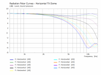
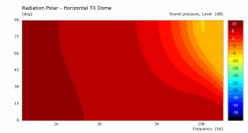
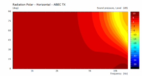
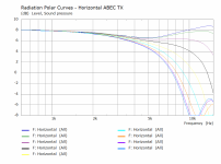
Here is the difference between the two tweeter diaphragm and surround curves that @augerpro posted before. There is a difference and the Tx Dome version does look to have less of a depression on axis and less severe dip off axis at 10K, but rolls off more in the top octave. When the attachments are open it is easy to flick backwards and forwards between them to more easily see the difference.
Attachments
If I understand you correctly, having a sharp edge at the back end might be a superior solution, as in my graphic... yes?I would be cautious about that conclusion. In a freestanding guide which effectively the donut would be, having the termination finish at the 180 degree mark or thereabouts tends to be a good thing overall, it works both ways, that other sources struggle to get past the termination in the other direction. When you round the back and make the curve go all the way around, that makes it much easier for rear sound to travel around and interfere with the front sound.
I grasp what you are saying... It is not something I had considered.
Attachments

Essentially, yes. Superior is a loaded word, but in this situation it might help in achieving the best compromise. In the opposite way to rounding the back corners of your box or turning the rear into a streamlined shape would reduce diffraction/directivity and might help smooth the transition to your woofer.
Simulation of freestanding guide with 180 degree termination over a woofer box (the woofer model is totally reflective so is a worst case scenario)
https://www.diyaudio.com/community/...aker-build-abec-modelling.357792/post-6510277
Simulation of freestanding guide with 180 degree termination over a woofer box (the woofer model is totally reflective so is a worst case scenario)
https://www.diyaudio.com/community/...aker-build-abec-modelling.357792/post-6510277
I’ve been reading through all the recent posts, and it looks like several of you are focusing on the simulated directivity below 1k. My intent with the sims was to ensure compatibility between the mid and the tweeter, particularly through the crossover region, so the sims shown in post #31 and #91 are not as fully representative as they could be. I just threw in the woofer response, and simulated it in the same plane as the mid and tweeter cabinet. I apologize for the confusion.
I have adjusted my VituixCad sims to account for the woofer bin placement and delay. The woofers are 68 cm behind the mid tweeter cabinet, and therefore the mid tweeter signal is delayed by 2 ms. This has an effect on the simulated directivity in the 100 – 500 Hz region.
Bevel Box


Donut


j.
I have adjusted my VituixCad sims to account for the woofer bin placement and delay. The woofers are 68 cm behind the mid tweeter cabinet, and therefore the mid tweeter signal is delayed by 2 ms. This has an effect on the simulated directivity in the 100 – 500 Hz region.
Bevel Box
Donut
j.
My point refers to the area highlighted in purple. The mid box is nearly 2dB more directive than the woofer box. It's not horrible but I think it could be smoothed if you want to go that far. The power response is humped from 250 to 700Hz.

Nice disscusion here.
To me all this leads slowly to "it-looks-like-a-Nautilus" shape...cones in teardrop spheres (with or without waveguide), softly merged in a vertical row without sharp transitions and corners between drivers....of course, not completely possible with diy bass boxes, but some smart rounding is doable in diy also....
In contrary to B&W 805 for example, where teardrop tweeter is bolted to the sharp edge of regular midbass baffle....that is so far away from Nautilus grandfather idea that is almost a negation of principle...
And then there are those dwarf looking Vivids which took principle to another level...
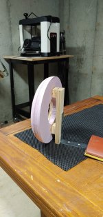
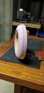
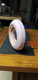
I am planning another round of prototype testing. I modified the donut to have a sharp termination at 180 degrees. I also plan to modify the bevel box to be closer to the kind of aesthetic shape I would want in a box format. I am still undecided on which shape/format I will build... hopefully these latest prototypes will give me a clearer direction.
j.
j.
Attachments
Thanks to @fluid, @Juhazi, @vineethkumar01, and @tmuikku for drawing my attention to the odd jump in directivity between 500-900 Hz.
I don’t believe this odd jump is related to the woofer, or the transition from woofer to mid. I think it is endemic to the mid driver and its cabinet. What follows is my reasoning:
First take note of the 12" woofer DI. This is a raw response, but DI is independent of filtering so any EQ I apply would not change the DI.
*

Next we look at the MW16TX-4 DI, as measured in its cabinet. Notice the jump in directivity between 500-900 Hz; it matches the full system simulation in this area.
*

I also have some recent data from an SB17CAC35-04, installed in a cabinet very similar to the TX system. Take note how the DI is much more smoothly increasing in the 500-900 Hz region compared to the MW16TX-4 data.
SB17CAC35-4
*

Next I substituted the SB17CAC35 into the full system simulation, and adjusted the eq and filters to get a reasonable response. The result is that the odd jump in directivity is smoothed out.
With SB17CAC35
*

With MW16TX

Now the really strange thing is that the two cabinets for the two mids are very similar.
The MW16TX-4 cabinet is 343 H x 254 W x 248 D (mm), with 37 mm radius edges on the sides, and a 37 mm 45 degree bevel on the top. The SB17CAC35 cabinet is 330 H x 254 W x 229 D (mm), with 37 mm radius edges on the sides, and a 50 mm 30/60 degree compound bevel on the top.
*

At this point I have several theories on why there is a difference, but I’m not really enthusiastic about any of those theories. My leading theory is that this is just inherent to the drivers. When I look at hificompass.com, and look at 6” – 7” drivers from ScanSpeak, SB, Seas, Purifi, I see that the off-axis response from 500-1k varies quite a bit driver to driver. If I look at the normalized off-axis response in the 30 dB scale, it is apparent to me that all of these drivers will have variations in power response and DI of +/- 2 dB from 500-1k.
I don’t believe this odd jump is related to the woofer, or the transition from woofer to mid. I think it is endemic to the mid driver and its cabinet. What follows is my reasoning:
First take note of the 12" woofer DI. This is a raw response, but DI is independent of filtering so any EQ I apply would not change the DI.
*
Next we look at the MW16TX-4 DI, as measured in its cabinet. Notice the jump in directivity between 500-900 Hz; it matches the full system simulation in this area.
*
I also have some recent data from an SB17CAC35-04, installed in a cabinet very similar to the TX system. Take note how the DI is much more smoothly increasing in the 500-900 Hz region compared to the MW16TX-4 data.
SB17CAC35-4
*
Next I substituted the SB17CAC35 into the full system simulation, and adjusted the eq and filters to get a reasonable response. The result is that the odd jump in directivity is smoothed out.
With SB17CAC35
*
With MW16TX
Now the really strange thing is that the two cabinets for the two mids are very similar.
The MW16TX-4 cabinet is 343 H x 254 W x 248 D (mm), with 37 mm radius edges on the sides, and a 37 mm 45 degree bevel on the top. The SB17CAC35 cabinet is 330 H x 254 W x 229 D (mm), with 37 mm radius edges on the sides, and a 50 mm 30/60 degree compound bevel on the top.
*
At this point I have several theories on why there is a difference, but I’m not really enthusiastic about any of those theories. My leading theory is that this is just inherent to the drivers. When I look at hificompass.com, and look at 6” – 7” drivers from ScanSpeak, SB, Seas, Purifi, I see that the off-axis response from 500-1k varies quite a bit driver to driver. If I look at the normalized off-axis response in the 30 dB scale, it is apparent to me that all of these drivers will have variations in power response and DI of +/- 2 dB from 500-1k.
Could be different length windowing in the measurements? distance from driver center to back edge is ~1ms and for example when taking 0deg measurement sound from back edge diffraction comes about ~2ms after direct sound due to round trip and gets partially windowed out. Haven't tested whats the magnitude of this error but as in general home measurements have some variation there. Merging with nearfield responses is another source for error, at which frequency one does it as vcad diffraction tool misses the back edge effect🙂
This is the MW16TX-4 off axis response from Hificompass.com (thanks @HiFiCompass)

Notice that from 300 to 500 Hz, the off axis is larger than the 0-axis, and then there is an abrupt change at 600 Hz and the 0-axis is higher. the responses merge together again at about 1200 Hz. This implies that the DI will rise by about 3 dB from 400 to 800 Hz... All of the 5" - 8" drivers have similar variations, and all of them are different.
j.
This kind of directivity variation could come from driver diameter and cone profile combined. I haven't checked maths...
In the MW16 measurement we can see low directivity at 600, 1200 and 3000hz
The speaker box dimensions will modify directivity too.
https://www.klippel.de/fileadmin/_migrated/content_uploads/KLIPPEL_Sound_Radiation_Poster_01.pdf

In the MW16 measurement we can see low directivity at 600, 1200 and 3000hz
The speaker box dimensions will modify directivity too.
https://www.klippel.de/fileadmin/_migrated/content_uploads/KLIPPEL_Sound_Radiation_Poster_01.pdf
Last edited:
Sorry I haven’t had a chance to read in detail; please excuse me if I repeat what has previously been suggested.
a few comments
One of the downside of the textreme cone's is that they are anisotropic.
Consider cone profile- flat piston vs convex vs concave vs convex with concave dust cap.
Consider baffle step losses
a few comments
One of the downside of the textreme cone's is that they are anisotropic.
Consider cone profile- flat piston vs convex vs concave vs convex with concave dust cap.
Consider baffle step losses
the typical cone edge resonance around 1kHz shows up in the directivity (cone edge out of phase)
If the odd jump in directivity seen in my simulations is a natural featue of the MW16TX driver, then it has no real impact on this project. I am only using the Satori data to assess the feasability of the project at this stage. I don't have any Purifi data yet because I have not completed my midrange box. The Purifi driver has a different blend of on/off axis performance in this region, so it would be very unlikely to have the same odd jump in directivity.
On the other hand, if the odd jump in directivity is a feature of my TX system cabinet dimensions, then I need to understand that so I don't inadvertently create the same condition again.
On the other-other hand, the TX system sounds extremely good, very natural, and it actually has the odd jump in real life (not just a sim), so I think the sonic impact of the odd jump in directivity is pretty small in my room.
As I said in the first post of this thread "One thing I have learned is that good DI, ER, and PIR response is important up to a point. Once some level of smoothness is achieved, once it is within +/- 2 dB or so of some target response, additional improvements do not mean much."
j.
The sound of a speaker in a room is a very complex set of interactions, a lot is known about which anechoic measurements help in improving the chance of something being preferred but there is no nice closed form equation that always gets it right.
Some things about directivity have obvious changes to the sound that are easy to pick and decide which you prefer. Other things are more subtle and don't sound like obvious flaws but over time show up as things you struggle to get along with. The circle of confusion of using material produced on other speakers to assess your current speakers can sometimes throw up some anomalies over time.
How accurate the measurements are plays a big part in how much faith you can put in tuning solely through them, taking truly representative measurements is not easy, so many small things can add up.
Simulation is great for looking at how acoustics works in a pristine environment. The interaction of width and depth in a cabinet coupled with front baffle shape is one of those things. BEM isn't great for cone depth and shape problems.
The same trait is visible in both the CAC and TX systems, it is impossible to match two very different sized enclosures perfectly. The CAC doesn't have the extra bump that makes it more obvious in the TX. I think it would be better to look at the family of off axis curves and polar charts to assess the impact more than the DI alone.
Just as the flat test baffle had unfortunate dimensions, it is possible to combine dimensions of the cabinet with a mid's natural low end directivity and make it worse. That is a hard thing to predict without a fully comprehensive model or test box. Does it matter? How can you know without actually testing it both ways over a long enough time to be sure.
Your point is well taken. Measurements, simulations, prototypes can get us part of the way there, but not the whole journey. Lately I have found that a nice smooth PIR curve that slopes down at about -1 db/octave is a good starting point for subjective voicing.
I am looking forward to testing my latest tweeter housing prototypes. Thanks for your thoughts !
I have several constraints on the design that will prevent me (or very likely to prevent me) from achieving an ideal power response in the region below 1k.The same trait is visible in both the CAC and TX systems, it is impossible to match two very different sized enclosures perfectly. The CAC doesn't have the extra bump that makes it more obvious in the TX. I think it would be better to look at the family of off axis curves and polar charts to assess the impact more than the DI alone.
I am looking forward to testing my latest tweeter housing prototypes. Thanks for your thoughts !
- Home
- Loudspeakers
- Multi-Way
- Purifi + Waveguide Project