For the 317, the voltage between pins 1 and 2 should be 1.25v. The 337 is close at 1.28v between output and adjust. That's good enough.
If the voltage measured directly across pins 1 and 2 still reads 1v, it's technically defective. Try measuring that voltage directly and not to ground.
If the voltage measured directly across pins 1 and 2 still reads 1v, it's technically defective. Try measuring that voltage directly and not to ground.
The regulators are doing as they should (regulating those voltages to 1.25v) so if the voltage is off (it should be ±13.75v) the resistors are either different from the diagram or out of tolerance. The output voltage is not so far out as to be causing a problem.
Do you have a 2 ohm current limiting resistor?
Are the source resistors within tolerance?
What value are the installed source resistors?
Do you have a 2 ohm current limiting resistor?
Are the source resistors within tolerance?
What value are the installed source resistors?
We'll find out whether it's good enough. I prefer resistor limiting over internal supply limiting because supply limiting can be unpredictable.
You will insert that resistance in the B+ supply line feeding the amp.
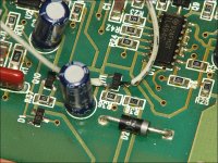
Find Q18 in your amp and jump is as the one in the photo is.
Will the amp power up and stay on with Q18 bridged?
You will insert that resistance in the B+ supply line feeding the amp.
Find Q18 in your amp and jump is as the one in the photo is.
Will the amp power up and stay on with Q18 bridged?
Attachments
This is what I need. I need the amp to remain on while drawing limited current so you can take some voltage measurements.
- Home
- General Interest
- Car Audio
- Punch X250.2 cycling