mpmarino said:Is this what your sending to Burningamp?
Does that matter to you? You're not going to be there anyway

Though you sure ought to! 😀
Magura 🙂
Magura said:
Does that matter to you? You're not going to be there anyway
Though you sure ought to! 😀
Magura 🙂
"wedding ............. "
hehe
that must be from wife's side of familly

( ZM , just came back from one such wedding party)
Zen Mod said:
nope - I'll send plain dreky preamp...
with beafier version I'll play when I receive first official pcbs
say , twice 25V and .................
I'm certainly not opposed to the idea!
"wedding ............. "
Nope, my side. One thing I've learned in my life is that family must come first. Yes, family before audio.
he he
mpmarino said:
...............
..........
Am I banned now??
not from that reason ,certainly ;
even if I can name a few different ones.......as having more Altec drek than me...........

mpmarino said:
Am I banned now??
I'll save you the humiliation, and ask a moderator to delete your post

Magura 😉
Magura said:
I'll save you the humiliation, and ask a moderator to delete your post
Magura 😉
mp edited his post too late , obviously 😉
HeHe all that OT... Well i am one of the greedy guy's, so i naturally got some more quistion's today.... ---------------------->
I stripped my single-sided PCB-layout down to 7jumperwire's now. The first pcb i made, i had a failure on schematics, that i diden't see, till it was all etched
Well nomatter, it's kindof fun to draw pcb's right ?
I am hoping to finish up Left channel pumpkin this weekend, and i would like some explanation about howto adjust this little bugger 😀
1. The WR1 is as i see it, a trimmer to adjust the balance between q1 and q2 right ???
I see, that the 'sliderleg' is connected to drain q10 etc... and that the two outherside's of the trimmer is connected to source's of q1/q2, how doe's this work ??? And how do i adjust it, i mean where to meassure, and how much ? ?
2 The WR2 is for adjustning the current source (again as i see it!), and again howto adjust, and where to meassure ? ?
3. Do i win something if i use a balanced attenuator, instead of a normal stereopot at the indput, when i got no balanced sources, and does it matter at all ???
Really be glad for prober answer 😀 Free beer two those who answer my quistion's at my place here in DK 😎
Jesper.
Schematic link here
lykkedk said:./..............
1. The WR1 is as i see it, a trimmer to adjust the balance between q1 and q2 right ???
I see, that the 'sliderleg' is connected to drain q10 etc... and that the two outherside's of the trimmer is connected to source's of q1/q2, how doe's this work ??? And how do i adjust it, i mean where to meassure, and how much ? ?
2 The WR2 is for adjustning the current source (again as i see it!), and again howto adjust, and where to meassure ? ?
3. Do i win something if i use a balanced attenuator, instead of a normal stereopot at the indput, when i got no balanced sources, and does it matter at all ???
....................
first No.2 :
preadjust R22 + WR2 to ~ 200E ; that will give you ~ 16mA through input LTP ,for start.....
anyway...................
with WR2 you can adjust currents through left and right output CCS-es (look at currents through R7 and R8) and - accordingly - offset between outputs AND GND
with WR1 you can decrease and null difference between + and - output (that's that- another one DC offset 😉 )
you can use one stereo pot per channel
or question was different?
in any case- tweaking both WRs is iterative process ; as Papa teaches/preaches in past - take it slowly 😉
edit :
you can pass all my beers to Lucky Luke
if I didn't answer on all Qs,ask again,please......
you can use one stereo pot per channel
or question was different?
No that's fine thanx a lot...
Thanx for nice answer's very cool.
And about the beer. Steen can come and listning + drinking beer with me, no problem. (He would like to take train back home i suppose then) 😀
Maybe.. (99%) 😉 I will be back later this week / next week... with new quistion's.
Have a nice evening.... ZenMod
Jesper.
BY ZENMOD : you can use one stereo pot per channel
or question was different?
ANSWER FROM ME : No that's fine thanx a lot...
I must had been mad... yesterday, replying that this was the answer i was searching for... sry. about that !... The thing i would like to know(s) is :
1 I assume i short GND and -in when using it unbalanced with no balanced sources ?
2 Can i then use +in from LEFT channel and +in from RIGHT channel, with a normal alps 4,7Kohm stereopot. ??? -- OR do i win somthing using a 4deck here ??? This is something i allway's find hard to figure out btw.
3 The BC546C ... I will match them for HFE, with a meter (multimeter) right ?
4 Also the j309 / irf610 / irf9610, need's matching, but not between parts right ? only pairs ?
That should be it i think !
Jesper.
lykkedk said:
I must had been mad... yesterday, replying that this was the answer i was searching for... sry. about that !... The thing i would like to know(s) is :
1 I assume i short GND and -in when using it unbalanced with no balanced sources ?
2 Can i then use +in from LEFT channel and +in from RIGHT channel, with a normal alps 4,7Kohm stereopot. ??? -- OR do i win somthing using a 4deck here ??? This is something i allway's find hard to figure out btw.
3 The BC546C ... I will match them for HFE, with a meter (multimeter) right ?
4 Also the j309 / irf610 / irf9610, need's matching, but not between parts right ? only pairs ?
That should be it i think !
Jesper.
1. yes ......
2. yes- normal stereo pot used for both channels........ as in any usual unbal preamp
3 . good enough ........
4. match between left and right........J309 .....IRF610 .....IRF9610
Cool ZenMod...
Then q1/q2 matched pair ? (j309)
Then q5/q7 matched pair ? (irf9610)
Then q6/q8 matched pair ? (irf610) .... Cool it should be doable.
Have a nice day.
Jesper
Then q1/q2 matched pair ? (j309)
Then q5/q7 matched pair ? (irf9610)
Then q6/q8 matched pair ? (irf610) .... Cool it should be doable.
Have a nice day.
Jesper
lykkedk said:Cool ZenMod...
Then q1/q2 matched pair ? (j309)
Then q5/q7 matched pair ? (irf9610)
Then q6/q8 matched pair ? (irf610) .... Cool it should be doable.
Have a nice day.
Jesper
yup
q1/q2 .....J309 or J310 or 2SK170V matched pair
q3/q4 .... whatever NPN bjt thingie you have .....(pinout!!) matched pair
q5/q7 .....9610 or 9510 ......matched pair
q6/q8......610 or 510 ......matched pair
q1/q2 thermaly coupled (face to face)
q3/q4 too ,
q5,q6,q7,q8,q10 on same heatsink
edit:
why not switch to toobz........ ?
they have more legs ...........
q1/q2 thermaly coupled (face to face)
q3/q4 too ,
q5,q6,q7,q8,q10 on same heatsink
😀 lookie lookie my friend 😉
Jesper 😎
Attachments
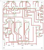
lykkedk said:
😀 lookie lookie my friend 😉
Jesper 😎
hehe
pretty clumsy .........
but- even like that, certainly better than any of ZM made pcbs
pretty clumsy .........
Yep, this is my first attemp to do layout with diptrace... Actually it's not very easy (pattern traces etc...) I think this layout is better than the first one i fcuk'et up, cause now i only got 7jumper's on the singlesided layout.
Well i tried to hold 'the power' at left side pcb, and place resistors near part's. But it's not near perfect, but i will try it out, and if no hum and other probl. i dont care, as long as it made prober.
One again thanx for your'e help Zenmod
Jesper.🙂
lykkedk said:
Yep, this is my first attemp to do layout with diptrace.............. 🙂
ZM:
but- even like that, certainly better than any of ZM made pcbs
Isen't this pcblayout-forum.com ??? 😕
uppsss... sry. for OT guy's 😀
mpmarino : You use batteripower for your'e pumpkin ? - Tell me about it 🙂
Jesper.🙂
uppsss... sry. for OT guy's 😀
mpmarino : You use batteripower for your'e pumpkin ? - Tell me about it 🙂
Jesper.🙂
lykkedk said:Isen't this pcblayout-forum.com ??? 😕
uppsss... sry. for OT guy's 😀
mpmarino : You use batteripower for your'e pumpkin ? - Tell me about it 🙂
Jesper.🙂
OT - he he. What does it mean? anyone?
My batt box is almost done but no Pumpy yet. I'll wait for Choky's boards - I have too much going on to scratch build and I would like to support greedy Papa Jr too.
- Home
- Amplifiers
- Pass Labs
- Pumpkin Preamp - Perfect for F4