The question is which part of the circuit is unstable?
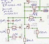
To begin fault finding, I would short the inputs to ground, then fit a shorting link across R1 & R3, this grounds the JFET gates and prevents any feedback, do you still have oscillation on the output?
To begin fault finding, I would short the inputs to ground, then fit a shorting link across R1 & R3, this grounds the JFET gates and prevents any feedback, do you still have oscillation on the output?
J1, J2 are both shorted to SGND and PGND.
I'll try shorting R1 and R3.
This is so frustrating.
SGND and PGND are connected via JP1
I'll try shorting R1 and R3.
This is so frustrating.
SGND and PGND are connected via JP1
Shall I work on the amp with 2.7X or 10X gain ?
what I wrote is for reducing of OLG
set gain ratio to adequate for your needs
I have good hope that reducing the resistors to the value Zen Mod suggested will help
I just remembered that two years ago when I tried my X0 clone (similar to Pumpkin) on perf boards I had a bad oscillation and I cured it by having 1k5 in series with the output after the cap and and 1k5 then to ground.....
Osci was gone.....
I just remembered that two years ago when I tried my X0 clone (similar to Pumpkin) on perf boards I had a bad oscillation and I cured it by having 1k5 in series with the output after the cap and and 1k5 then to ground.....
Osci was gone.....
what I wrote is for reducing of OLG
set gain ratio to adequate for your needs
So its makes no difference which one of the Pumpkins I am playing with?
Ultimately both will be set to 2.7X gain.
I'm just trying to keep one as close as possible to design spec so that there are not too many unknowns.
I have good hope that reducing the resistors to the value Zen Mod suggested will help
I just remembered that two years ago when I tried my X0 clone (similar to Pumpkin) on perf boards I had a bad oscillation and I cured it by having 1k5 in series with the output after the cap and and 1k5 then to ground.....
Osci was gone.....
I think I've ruled out the Shuntkys. Even our avenues into LM317/LM337 regulators hasn't improved things one iota.
Original PCB problems were with the Pumpkins anyway. I never had a problem with the Shuntkys.
I'm not going to do it tonight cos I've had a few beers. I'll report back in the morning.
I won't be able to read your post until late tomorrow evening.
If you still have oscillation on the output, and the output from the cascode (Q3 Q4) is clean, the solution may be as simple as increasing the value of R9 & R14 to 470 Ohms.
Another experiment for the morning. Thank you for the comments - fuel for experimenting. Ill keep you informed.
Original PCB problems were with the Pumpkins anyway. I never had a problem with the Shuntkys.
that is a good news concerning the shunties, maybe you can use them again later.....
(not Shuntkys) ! it comes from shunt! But may be you take it as joke to call it "shantkys" to give Zen Mods work a more russian flavor......😀😀
and I think the circuit of Pumpkin ZM made is very good and I hope that you have no more pcb problems with Pumpkin and can cure the oscillations with reducing the output resistors and enlarging the output load.....
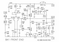
..... what did Nelson say with BA-3
"We have a saying in my house (lifted from Cesar Milan) that “A tired puppy is a happy puppy.” It is my experience that sometimes you get subjectively better sound from a gain device which is operated at a significant portion of its capacity – not allowed to loaf around with an easy job. We may find that it sounds better if we make it do some work. There's nothing magic about this. Making a gain device traveling a load line that represents real work gives it some character. Your mother would probably agree."
hope it will help in your case.....
My stocks of low pF caps are nil. Consequently I'm having to buy nnew values every time.
where did you put the twisted pair (PSU wiring perhaps). What value did you substitute for C1/C2 ?
You can use some twisted pair wire like CAT5 which is around 17pf/ft, then you can order the value caps that you need when you get it trimmed.
I know you are getting lots of suggestions, so here is one more. Simply load both outputs past the output caps at J3,J4 with what ever resistance you choose then you have effectively reduced the AC gain of Q5 and Q7 by loading the outputs with R13 and the loading resistor on the minus output and R14 and the loading resistor on the positive output. This wont effect your dc biasing because of C4 and C5. No desoldering!
Are you grounding the unused inputs and outputs? I could have missed those posts.
By the way I have my Pumkins still on a board and have them hooked up to my test gear.
One thing to mention is without balanced outputs the distortion was about .5% at 1VAC and balanced out about .03% at 1VAC (I'm using a balanced to unbalanced transformer for my balanced measurements). It really likes to be run balanced out.
BDP
OK, in no particular order I have tried all the suggestions.
1. Adding a 4K7 load to both +out and -out makes no difference to the oscillations.
2. Shorting R1 and R3 KILLS the oscillation . +IN and -IN are GROUNDED.
3. Replacing R2 and R4 with 2K7 and connecting 2K7 between Q3(c) and Q4(c) makes no difference to the oscillation.
As this pumpkin now stands.
Everything is AS PER SCHEMATIC except R2 and R4 are now 2K7. R5 and R6 are 27K. C1 and C2 are 33pF. there is a 2K7 as in (3). There are two 4K7 load resistors (one +OUT to GND - the other -OUT to GND).
my suggestion was like this......
I tried that approach, all it did was attenuate the oscillations at the output.
The oscillations were still occurring.

brave katieandDad,
last suggestion put the small cap of the same value as the feedback cap in the input, Papa uses it the input of BA-1 fronted, I know it is for CMRR, but who knows........
BRAVE - I DESERVE A MEDAL.
Unfortunately placing 33pF caps from Q1 and Q2 gates to SIG GND only serves to attenuate the oscillation slightly.
Just to reiterate where we are.
Everything is still as per the schematic except:
R2 and R4 have been reduced to 2K7
There is a 2K7 between Q3(c) and Q4(c)
R5 and R6 are reduced to 27K
C1 and C2 are increased to 33pF
There are 2 x 33pF between Q1(g) and GND and Q2(g) and GND
There are two 4K7 load resistors between +OUT and GND and -OUT and GND.
IN+ IN- and SIG GND are shorted together.
JP1 is fitted shorting SIG GND to PWR GND.
I appreciate that C1, C2 and the two extras should be 15pF but I'm not spending any more money on this thing until I get somewhere.
- Home
- Amplifiers
- Pass Labs
- Pumpkin preamp - ordered by Steen , official making thread