It would be helpful if you indicate attempts at humour with a smiley. On this site it can be difficult to distinguish between humour and and error.drlowmu said:People act as though feedback is acceptable, it isn't !! Imagine putting an after-the-fact, out-of-time signal back into a prior stage, that has already processed the musical event, and is processing NEW and fresh. different information.
Are we STILL in the dark ages, to accept out-of-time signal processing ?? Not for my ears, thank you very much.
No, the bigger the cap the more accurate is the sound. This can only be considered "worse" if hi-fi sound reproduction is not your aim. I note the smiley; is this another attempt at humour?Also the bigger the cap, the worse is the sound on a Loftin White SET 2A3 amp, proven 100 times over, the last 27 years. That is just the way it is. 🙂
Yes, maybe. Anyone who can do algebra has no excuse for this error. Anyone who cannot do algebra has nothing useful to say about feedback.piano3 said:Rundmaus, this idea of feedback as regurgitated information appears to be widespread; perhaps as an attempt to explain in a non-scientific way the (audible) effects of badly applied feedback.
From personal experience these things are vital for sound outcome.
1. Use quadratic cores for chokes and power transformers. Because of lower DC resistance at the end. For more power - use bigger laminations but squared core, not just add laminations and increase Sf this way... Simple lenght of the turn is smaller.
.
2. Design and build chokes first. Because You will have exact Rdc values for voltages drop and more precise datas to design power transformer.
.
2a. All power transformers should be designed to have 1T induction of primary OR even less
0.707 cca. That means we end up with higher number of turns in primary also leeds to proportionally higher number of secondary turns. But that transformer will act much better and without overheating.
.
2b. use a bit wider wire - leeds to possibile increase the cores...
.
3. If You have chance use U frame laminations with better isolation of P to S. for all power trans.
.
4. Separate power transformers for High voltage, for any Direct hated tube and for rectifier.
Not ALL-in one.
.
5. DHT tube trans. with C.T and close to the tube under. C.T is kathode now. Do not use external P.S. and have 2 x 0.5m from and to, back and forth, cathode of DHT...
.
6. place all chokes as far as possibile from power transformers.
.
7. do not use bleeders. If You vant to discharge caps do this in some other way. Using of bleeders parallel with caps in PS in SE design somehow destroying the magic and sparcle... 🙂
.
8. Someone is mention before, do not use R in serial in the PS path. Infact do not use any R in the power supply if it is possibile and it is with propper planning.
.
9. Use CL input. But with very small C after rectifier, circa 10nF to 47-100nF max. BUT higher voltages 1500V minimum ! That is not pure CL but rather L input. Follow with 2 stages low resistance L higher inductivity as much. And with propper gap. Not to saturate.
.
10. mind the relative permeability of core laminations use rather lower than higher, higher leave for output trasnsfrmers... 🙂
.
11. mono block form is somehow logical end because of the mass, volume and ergonomic point (with shortening the speaker cables and better separation) One time tried, implicate to think in the way to go to the source with mono block design 🙂
.
sorry for preaching, but this is personal thinking nd some outcome from built-and-listen
most of these valid for preamplifiers too. As the tube more exotic and DHT these points becomes more vivid...
cheers 🙂
I forgot..
do not mount any transformer or choke directly to the chassis. Isolate any direct contact. Then, each one deserving grounding, ground with separate wire to one point. EACH capacitor in PS too. 🙂 This point of ground should be close to the first input tube cathode. After that connect this point to chassis ground. (This way I made one preamp before few months - no hum or anything...)
do not mount any transformer or choke directly to the chassis. Isolate any direct contact. Then, each one deserving grounding, ground with separate wire to one point. EACH capacitor in PS too. 🙂 This point of ground should be close to the first input tube cathode. After that connect this point to chassis ground. (This way I made one preamp before few months - no hum or anything...)
A bit of unmarked humour sneeked in among mostly helpful advice?Zoran said:7. do not use bleeders. If You vant to discharge caps do this in some other way. Using of bleeders parallel with caps in PS in SE design somehow destroying the magic and sparcle...
A good way to make a high impedance supply, by putting it right on the boundary between choke input and cap input; thus getting the worst of both worlds. With a supply like this, you don't need to add an extra resistance as the supply will have a high enough impedance anyway. Why someone would want a high impedance supply is beyond me (except for a guitar amp); wait a minute - it will maximise the music envelope IM which some people seem to confuse with good dynamics. OK, now I understand; this is an FX box pretending to be an amplifier.9. Use CL input. But with very small C after rectifier, circa 10nF to 47-100nF max.
Isn't the output impedance maximised at around a microfarad or so, but low in the region up to a few hundred nanofarads?
I don't think that is the intention. The capacitor is shorting noise from the secondary and will reduce Voltage swings across the choke when the rectifiers cut it off. If the first capacitor raises the output Voltage it is too large.A good way to make a high impedance supply, by putting it right on the boundary between choke input and cap input
Combined with some damping/snubbing of the transformer, some HF suppression and a large enough cap at the end, this stage leaves only a little ripple with the DC. A second inductive stage is hardly neccessary. Low supply impedance can be offered later in the supply.
Attachments
Last edited:
It's been my contention that aside from supply rejection and feedback like you say, the wanted capacitance is more or less the same (pp or se). When cost and size is no object, that would be the reasonable thing.IM is the issue, including the 'DC' from second-order which will vary like the music envelope. This needs bigger caps, or an amplifier which does not vary its gain with supply rail voltage.
Would you agree that using the larger ones anyway, (despite the result being comparable either way), prevents the disturbance from coming into contact with as many other elements? If the ideal place to fix all aspects of this problem is by using a certain size of cap, xouldn't introducing them to the feedback loop bring a mixed bag?So small PSU caps are fine provided you use enough feedback in your amp.
People act as though feedback is acceptable, it isn't !! Imagine putting an after-the-fact, out-of-time signal back into a prior stage, that has already processed the musical event, and is processing NEW and fresh. different information.
Are we STILL in the dark ages, to accept out-of-time signal processing ?? Not for my ears, thank you very much.
Well then I had better stop using triodes with their internal negative feedback. I guess I'll have to start designing with tubes that have screen grids to break that feedback loop. I don't want out-of-time signal processing to corrupt things within the same stage either.
Perhaps. If it boosts voltage, it boosts impedance.piano3 said:Isn't the output impedance maximised at around a microfarad or so, but low in the region up to a few hundred nanofarads?
If enough current is taken from the supply then the choke will never be cut off so there is no need for the input cap. If insufficient current is taken from the supply then the impedance will already be high. Hence the cap is an attempt to patch up a situation which should not occur.AllenB said:I don't think that is the intention. The capacitor is shorting noise from the secondary and will reduce Voltage swings across the choke when the rectifiers cut it off. If the first capacitor raises the output Voltage it is too large.
Sorry, I don't understand what you are saying.Would you agree that using the larger ones anyway, (despite the result being comparable either way), prevents the disturbance from coming into contact with as many other elements? If the ideal place to fix all aspects of this problem is by using a certain size of cap, xouldn't introducing them to the feedback loop bring a mixed bag?
Everyone knows that triode feedback is not really feedback, or happens instantaneously (unlike other forms of evil negative feedback). 😎SpreadSpectrum said:Well then I had better stop using triodes with their internal negative feedback.
Hi,
People act as though feedback is acceptable, it isn't !!
Um Jeff... no disrespect, but in your direct coupled 2a3 designs there's lots of feedback. 🙂
I think we need to distinguish the difference between Local and Global feedback. There is quite a lot of misconception out there. I will make a very rough summary below that will no doubt be dismissed by others as they see fit. 🙂
Local Feedback- pretty much not desirable, but often unavoidable. Its not desirable since distortions introduced are magnified through subsequent stages, which often also introduce additional distortions... One of the most common ways to create a local feedback loop in a differential amplifier is to bypass the cathode with a capacitor.
Global Feedback- very useful if implemented well. Which says that if it is not implemented well, then it is not very good. This kind of feedback (when implemented correctly) actually can reduce THD but more importantly (for me at least) increases damping.
Also, Global Feedback (when properly implemented) does not influence transient recovery time.
Best regards
Ian
Last edited:
Hi,
I' m following this interesting discusion and allthough I feel rather
uncomfortable to pop in among qualified people, I would appreciate
if you could take the time to answer my novice query.
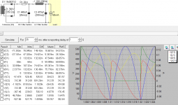
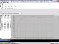
I can only rely to PSUD for designing power supplies and I was
aiming for fast rising time because I thought this would be a low
impedance psu. Of course, ripple has to be low too so I would get
something like the first pic with a 94μF final capacitor. Inevitably,
the voltage will sag on suddent current demant. I simulated the same
psu with a 500μF final capacitor - second pic - and the same sag
will occur but with a slower rate and it will be followed by a slower
recovery time. I think both situations will be audible in a different way.
Could one of them fool our brains more effectively?
Also, I read in voltage regulators datasheet that bigger output capacitors
improve transient response. But regulated voltage supposedly doesn't shag,
or does it? Could be something else beside voltage stability?
I' m following this interesting discusion and allthough I feel rather
uncomfortable to pop in among qualified people, I would appreciate
if you could take the time to answer my novice query.
I can only rely to PSUD for designing power supplies and I was
aiming for fast rising time because I thought this would be a low
impedance psu. Of course, ripple has to be low too so I would get
something like the first pic with a 94μF final capacitor. Inevitably,
the voltage will sag on suddent current demant. I simulated the same
psu with a 500μF final capacitor - second pic - and the same sag
will occur but with a slower rate and it will be followed by a slower
recovery time. I think both situations will be audible in a different way.
Could one of them fool our brains more effectively?
Also, I read in voltage regulators datasheet that bigger output capacitors
improve transient response. But regulated voltage supposedly doesn't shag,
or does it? Could be something else beside voltage stability?
Attachments

Hi,
People act as though feedback is acceptable, it isn't !! Imagine putting an after-the-fact, out-of-time signal back into a prior stage, that has already processed the musical event, and is processing NEW and fresh. different information.
Are we STILL in the dark ages, to accept out-of-time signal processing ?? Not for my ears, thank you very much.
Also the bigger the cap, the worse is the sound on a Loftin White SET 2A3 amp, proven 100 times over, the last 27 years. That is just the way it is. 🙂
Jeff
its not the dark ages if you use neg. feedback.
Granted, I use it the way it supposed to be used: as a form of gain control. But I make mic preamps, compressors and limiters instead of audio reproduction amps normally.
But those audio amplifiers that people are discussing in this thread don't really need negative feedback.
So I can see your angle can be justified.
I make all my circuits without negative feedback first. That is the only way I know how to debug noise/hum issues. Then if I need to install a gain control, I'll apply the circuit.
Hi,
I' m following this interesting discusion and allthough I feel rather
uncomfortable to pop in among qualified people, I would appreciate
if you could take the time to answer my novice query.
I can only rely to PSUD for designing power supplies and I was
aiming for fast rising time because I thought this would be a low
impedance psu. Of course, ripple has to be low too so I would get
something like the first pic with a 94μF final capacitor. Inevitably,
the voltage will sag on suddent current demant. I simulated the same
psu with a 500μF final capacitor - second pic - and the same sag
will occur but with a slower rate and it will be followed by a slower
recovery time. I think both situations will be audible in a different way.
Could one of them fool our brains more effectively?
Also, I read in voltage regulators datasheet that bigger output capacitors
improve transient response. But regulated voltage supposedly doesn't shag,
or does it? Could be something else beside voltage stability?
actually, you want "springy" instead of "stiff"
like a 20 uf then a 8H in series and 20uf with something like a 5v4 or 5u4 rectifier.
of course there is other combinations. I imagine Dr Lowmu has some better examples of this beside the one that poured out of my head. I would do a search on this site for his post on the subject.
From where did you get the peculiar notion that NFB is "supposed" to be used for gain control and not other things? It was not invented for gain control, but for distortion reduction (both non-linear distortion and frequency response flatness).DavesNotHere said:Granted, I use it the way it supposed to be used: as a form of gain control.
They do need it if their gain depends on supply rail voltage, and their supply rail voltage depends on how loud the music has just been.But those audio amplifiers that people are discussing in this thread don't really need negative feedback.
Hi-fi sound reproduction needs either a stiff supply (one which doesn't sag) or enough negative feedback that supply rail sag doesn't affect gain. If the aim is not hi-fi then you choose whatever suits your tastes.actually, you want "springy" instead of "stiff"
From where did you get the peculiar notion that NFB is "supposed" to be used for gain control and not other things? It was not invented for gain control, but for distortion reduction (both non-linear distortion and frequency response flatness).
They do need it if their gain depends on supply rail voltage, and their supply rail voltage depends on how loud the music has just been.
Hi-fi sound reproduction needs either a stiff supply (one which doesn't sag) or enough negative feedback that supply rail sag doesn't affect gain. If the aim is not hi-fi then you choose whatever suits your tastes.
Obviously you haven't learned enough yet DF96
Don't be giving people bad advice, because I don't have the time to police and undo your bad "theories" and "applications"
NONE of the advice given here by DF96 is bad. It may not be advice that some here would choose to agree with, but there are distinct elements in this thread that come across almost as an expression of blind belief rather than facts based in simple electrical and electronic theory.Obviously you haven't learned enough yet DF96
Don't be giving people bad advice, because I don't have the time to police and undo your bad "theories" and "applications"
I have sat on the sidelines here, but nothing that DF86 said in his last post was incorrect. To describe it as bad advice is to fail to understand the intention. If someone wants to build a circuit that pleases them because they like the way it sounds, or they like the way it works, or if if they want to use a certain topology, then that's absolutely fine. However, the claims made by some others in this thread in support of fundamentally poor engineering practices just boggle the mind. DF96 is merely trying to show them that what they may believe to be "a good thing" may only appear to be a good thing, when in fact the opposite may actually be the case.
Yes, there are a number of trained physicists, chemists, mechanical and electrical engineers on this forum whose expert advice is routinely disrespected.
Wouldn't it be better to fix the problem by using a larger cap, than to pass it around the amp.. ie, apply feedback but size the cap as if there were no feedback available?Sorry, I don't understand what you are saying.AllenB said:Would you agree that using the larger ones anyway, (despite the result being comparable either way), prevents the disturbance from coming into contact with as many other elements? If the ideal place to fix all aspects of this problem is by using a certain size of cap, wouldn't introducing them to the feedback loop bring a mixed bag?
None of us has learned all there is to learn. Some of us are aware of this.DavesNotHere said:Obviously you haven't learned enough yet DF96
That is a pity. I always welcome a detailed refutation when I get something wrong, because that is how I learn.Don't be giving people bad advice, because I don't have the time to police and undo your bad "theories" and "applications"
Huge caps can bring their own problems, such as inrush currents and power wasted in bleeders. Over-engineering can solve one problem and create two others which then need to be solved too. That is why all engineering involves compromise.AllenB said:Wouldn't it be better to fix the problem by using a larger cap, than to pass it around the amp.. ie, apply feedback but size the cap as if there were no feedback available?
Hi,
I' m following this interesting discussion and although I feel rather
uncomfortable to pop in among qualified people, I would appreciate
if you could take the time to answer my novice query.
I can only rely to PSUD for designing power supplies and I was
aiming for fast rising time because I thought this would be a low
impedance psu. Of course, ripple has to be low too so I would get
something like the first pic with a 94μF final capacitor. Inevitably,
the voltage will sag on sudden current demand. I simulated the same
psu with a 500μF final capacitor - second pic - and the same sag
will occur but with a slower rate and it will be followed by a slower
recovery time. I think both situations will be audible in a different way.
Could one of them fool our brains more effectively?
Also, I read in voltage regulators datasheet that bigger output capacitors
improve transient response. But regulated voltage supposedly doesn't shag,
or does it? Could be something else beside voltage stability?
You can not use solid state devices in a Loftin White amp, and have any reliability long term due to start up problems. Also, avoid cap input filters, after the rectifier. Also, do not use R/C networks to filter the B+ to the Finals stage. Here, you seek MINIMUM series resistances, the GOOD goal, reduce series resistances in the B+ filter to a minimum, especially to 2A3 finals.
To test a supply in PSUD, allow it to start up and stabilize, then do a 15% ( arbitrary ) current step, and see how the supply responds. How the supply starts up, from turn on, has little to do with the " sonics" process, assuming one uses proper rated parts and a good design.
I would like to propose to you, that the supply for a 2A3 Loftin White amp, should not have any Ls higher than 20 Ohms DCR , nor employ any Cs larger than 50 uF in any one spot !! Large caps, 93 uF, or 500 uF, in the B+ ruins the dynamic capability of the amp, because the large cap ROBS the tube of instantaneous energy, on peaks, and it truncates dynamic contrasting, as heard by our EARS and brain. Also, low ripple is NOT too important to the low gain Finals 2A3 stage, anything 800 mVAC or less will be fine. Low ripple is very important to the high mu Driver stage however. !! I shunt regulate my Driver stage with just a single part. Uber stable.
Email me and read the two EEs ( Hasquin and Swenson ) prior comments on power supply design, using " fast " supplies. It will put a new ( and refreshing ) light on the subject. It works, on a speaker, like gangbusters !!
I am at drlowmu@gmail.com. Lotsa PSUD in what I will send you.
Do not worry about the conventional " experts" on the Forum at all.
Jeff
Last edited:
- Status
- Not open for further replies.
- Home
- Amplifiers
- Tubes / Valves
- PSU with Choke for Loftin-White 2A3