Help needed
I have made my first PSU like in a diagram. I have cheap tpa3118 d-class amp and tangband w3-871SC connected to it.
Has someone a clue why i have constant noise coming from the speaker even though i have no signal connected to my amp.
The noise is so loud that i can hear it from two meters away from the speaker.
I am suspecting my psu, should i try to filter this noise somehow.
Attachments
Power supply looks fine. No need for the 0.1uF caps or the 10R in series with one of them. Place the 0.1uF decoupling up against to amplifier to ground. Check your earth/grounding point.
What do you mean by "noise"? Random white noise, oscillation, buzz, hum? What makes you think the PSU is the source of the noise? Far more likely is parasitic oscillation in the amplifier.
There are many reasons for hum/noise. They are mostly related to grounding. If you have a picture of your implementation (and/or a grounding scheme), it will be easier for others to debug.
Open inputs? Connect to source or connect inputs to gnd. Inputwires and all wires basicly to and from ampboard should be tightly twisted, I don't mean you should twist psu wires with inputsignal wires and speaker wires, each separately.
If ampboard is set at very high gain, own noise could be audible too. Especially when speakers do not have Zobel, but like Tangband have 50-100 ohm impedance at filterfrequency, causing treble frequencies (audible from ~4kHz) to be boosted.
If ampboard is set at very high gain, own noise could be audible too. Especially when speakers do not have Zobel, but like Tangband have 50-100 ohm impedance at filterfrequency, causing treble frequencies (audible from ~4kHz) to be boosted.
Thank you for many answers
I would define the noise as buzz/hum
I connected the input, but i still have some buzz/hum
I haven't done any groundings, so i think I should work with that. My connections are exactly like in diagram.
I would define the noise as buzz/hum
I connected the input, but i still have some buzz/hum
I haven't done any groundings, so i think I should work with that. My connections are exactly like in diagram.
Thank you for many answers
I would define the noise as buzz/hum
I connected the input, but i still have some buzz/hum
I haven't done any groundings, so i think I should work with that. My connections are exactly like in diagram.
Buzz and hum are two different things, different causes and different cures.
Hum is generally understood to be mains signal, 50 (60) Hz and sounding sort of 'pure' because it is pretty much a sine wave.
It is mostly caused by radiation from mains leads and such, NOT from the power supply. Cure is often redress of wiring and/or shielding of xformers.
Buzz is generally meant to be some form of rectified mains, mostly triangle-shaped, with higher harmonics and sounding more with 'rattles' and sharp undertones. Cuase of often issues in hrounding of various parts to each other or together. Cure is to review and rationalise the grounding scheme. I know, that's easier said then done but let's first find out what the problem exactly is.
Jan
Exactly? People often get grounding wrong. The PSU circuit looks OK, apart from the unnecessary snubber on the output and the unnecessary bypass cap across the reservoir.Jusalmi said:My connections are exactly like in diagram.
Exactly? Your amplifier is not shown at all.
Connected to where?
Some: do you mean less than before connection?
Did you try to turn down volume?
I connected the input, but i still have some buzz/hum
Connected to where?
Some: do you mean less than before connection?
Did you try to turn down volume?
Last edited:
The TPA3118 Chip has about 65 dB power supply rejection ratio. The Tang Band driver is 8 ohms and 87 dB per watt. A 10,000 uF capacitor loaded by a 35 mA draw will have about .035/(.01 x 120) or .029 volts of ripple. That would be .0001 watt or -40 dB. So the hum should be = 87 -40 -65 or -18 dB at 1 M. This and the harmonics should be just audible at a distance to the loudspeaker of .25 M.
That is with the input shorted.
That is with the input shorted.
Volume level doesn't have any effect on noise
Noise level decreased maybe a 30% when I connected signal input to my chip amp.
I Connected the input to:
TV spdif out --> optical cable --> optical spdif to analog converter --> RCA-cable --> chip amp signal input
I am using this amp:
TPA3118 PBTL Mono Digital Amplifier Board Module Sound Quality Audio Power amplifier Module *60W Power AMP DC 8 24V-in Instrument Parts & Accessories from Industry & Business on Aliexpress.com | Alibaba Group
Optical-analog rca converter:
Digital Optical Toslink Coax to Analog R/L/RCA Audio Signal Converter Adapter Wholesale-in Consumer Electronics on Aliexpress.com | Alibaba Group
If you have buzz with no signal connected then the source of that signal is irrelevant.
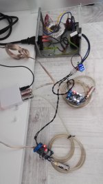
We need to see exactly what you have done, as details matter. You are probably injecting charging pulses into your audio, either directly via poor grounding or indirectly via magnetic induction.
We need to see exactly what you have done, as details matter. You are probably injecting charging pulses into your audio, either directly via poor grounding or indirectly via magnetic induction.
Gain of that ampboard is either 32dB or 36dB and set with r27/r28. I don't know how high the output from your dac is, but I think normally around 2Vrms ??? If normal I would remove r27, then gain becomes 20dB, for me that is high enough with my dac and cdplayers.
You have 2 signals, left and right, and that amp module is mono, but you didn't mention how many modules you have and how you connected them. There can be a ground loop. Also you didn't mention PSU of the digital to analog converter (it is as important as the PSU of the amplifier).
You still didn't show any detail about the GND connections, and if you tried to short amp inputs directly or not, and with what result.
The problem is definitely in connections of the system, but it is not shown yet at all.
If you use an RCA cable, then you have GND (outer ring). RCA cable is shielded (unless it's a cheap junk), so you have a grounding/shielding system already, but we don't know what is it like.
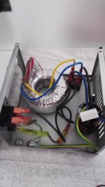
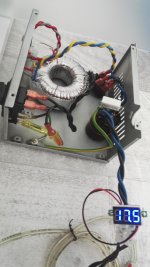
As suggested, you need to show a picture or two of how you implemented the circuit.
That 10,000uF is going to demand quite large charging pulses so you need to take the output directly from its terminals, a common error is to wire from the rectifier instead. Also when you are pulling fairly large load currents from the bridge rectifier, the rectifier will produce very short duration spikes which will go through anything, including any regulators you may have. Answer is to fit something like a 220nF capacitor across the transformer wires connected at the bridge rectifier. These spikes can be quite large so think 400V minimum working for the capacitor.
That 10,000uF is going to demand quite large charging pulses so you need to take the output directly from its terminals, a common error is to wire from the rectifier instead. Also when you are pulling fairly large load currents from the bridge rectifier, the rectifier will produce very short duration spikes which will go through anything, including any regulators you may have. Answer is to fit something like a 220nF capacitor across the transformer wires connected at the bridge rectifier. These spikes can be quite large so think 400V minimum working for the capacitor.
And did you have same noise when shorting the inputs ? So non shielded non twisted wires everywhere... combined with classD that might mean radiotransmissions.
- Status
- Not open for further replies.
- Home
- Amplifiers
- Power Supplies
- PSU noise