The only time, when the size of the supply capacitors determines the current is at initial charging. During operation of an amplifier the currents through the capacitors do not depend on their capacitance, but only on the amplifier's current draw.As I recall from simulations with 0.1 ohms for the transformer, you get about 25% higher currents going from 10,000 to 50,000 with a 40 volt transformer. That's not huge, but it's a lot more significant than what's shown in the linked table.
Can you be a bit more specific on the source for that?Several authors, such as Self, have documented bigger caps generally increase problems from ground currents, diode noise, and EMI in real world amplifiers.
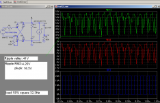
The ripple voltage changes with the amount of current, not with the frequency at which current is drawn.
Too bad, but reality doesn't agree with you. You have totally missed the point and are instead posting loads of irrelevant formulas.
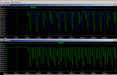
Waveforms attached. Clearly load current frequency does make a difference. Average current is 10A in both cases, but ripple voltage is double at low frequency.
Attachments

Last edited:
It does not seem very efficient to make simulations of a simulation of an amplifier, especially if you don't make it right. Do you enjoy listening to 20 A square waves?
Schematic

Green - non-bridged amplifier
Red – bridged amplifier
Current through load ~1 Apk sine
Capacitance per rail 22 mF
40 Hz

1 kHz

Ripple voltage and ripple current are higher for the bridged amplifier and there is no advantage at lower audio frequencies.
Schematic
Green - non-bridged amplifier
Red – bridged amplifier
Current through load ~1 Apk sine
Capacitance per rail 22 mF
40 Hz
1 kHz
Ripple voltage and ripple current are higher for the bridged amplifier and there is no advantage at lower audio frequencies.
Hey, why did you give the bridge amplifier one fourth the energy storage of the non-bridged one? You can't cheat that much! 😉
Half bridge - C2, C3: ~30V 22mF ea. - 20J energy storage
Half bridge - C8, C9: ~15V 22mF ea. - 5J energy storage
Try doubling C8, C9 to 44mF and you'll have half the storage in the bridged one compared to the non-bridged amplifier. Or even better - replace them with the equivalent single 22mF 30V across rails, use a single 24V RMS based supply, and make a virtual ground for the signal ground instead.
Also take a look at what happens if you give them the same energy storage.
It was a simulation of a power supply, not an amplifier. You said that the frequency of the current drawn from a power supply doesn't matter for ripple voltage. I showed that it does. Even more interesting is that the ripple voltage is somewhat lower when 20A DC is drawn than when the 10A average current (20A when on) square wave is. Although the square wave only draws half the power of the DC load, ripple voltage is higher!
~
Half bridge - C2, C3: ~30V 22mF ea. - 20J energy storage
Half bridge - C8, C9: ~15V 22mF ea. - 5J energy storage
Try doubling C8, C9 to 44mF and you'll have half the storage in the bridged one compared to the non-bridged amplifier. Or even better - replace them with the equivalent single 22mF 30V across rails, use a single 24V RMS based supply, and make a virtual ground for the signal ground instead.
Also take a look at what happens if you give them the same energy storage.
It does not seem very efficient to make simulations of a simulation of an amplifier, especially if you don't make it right. Do you enjoy listening to 20 A square waves?
It was a simulation of a power supply, not an amplifier. You said that the frequency of the current drawn from a power supply doesn't matter for ripple voltage. I showed that it does. Even more interesting is that the ripple voltage is somewhat lower when 20A DC is drawn than when the 10A average current (20A when on) square wave is. Although the square wave only draws half the power of the DC load, ripple voltage is higher!
~
Last edited:
Hi,
an interesting, vivid discussion...
Ripple voltage is the magnitude of fluctuation in DC output voltage at a specific output current, the difference between the minimum and peak supply voltage. Ripple voltage increases with capacitor discharge, which occurs as the voltage drops below the peak value; a longer filter time constant gives better smoothing, a complete discharge means no smoothing.
The value of the ripple voltage is dependent on load current, power supply frequency (period of the ripple signal) and capacitor value:
Ripple voltage = load current x diode off time / filter capacitor.
The ripple frequency output of a full-wave rectifier is twice as high as the input AC signal frequency.
A larger capacitor shortens rectifier conduction period.
You can't cheat that much!
Sorry, I didn’t take into account that you neither believe in those formulas nor the knowledge of several decades and therefore cannot correctly deduce the behaviour of 44 mF and 88 mF from the plots with 22 mF.
First I modified the RC circuit you used in your square wave simulation, although your version favoured the non-bridged amplifier. But cheating is not, what I usually do. The filter is now set so, that the DC offset is filtered out and does not enter the rms calculation.

Here are the corrected values that belong to post #43.
40 Hz

1 kHz

Now here are simulations with increased capacitance for the bridged amplifier.
44 mF per rail 40 Hz

44 mF per rail 1 kHz

88 mF per rail 40 Hz

88 mF per rail 1 kHz

What do they show? The bridged amplifier achieves the same ripple voltage as the non-bridged with double the capacitance at 40 Hz. However at 1 kHz it takes four times the capacitance for that. This is probably, what you meant, when you talked about an advantage at lower frequencies. It is indeed more like a disadvantage of the non-bridged amplifier, because the ripple voltage does not improve in the bridged amplifier. It worsens in the non-bridged.
Before you rejoice, even with that amount of capacitance the bridged amplifier still has not reached the performance of the non-bridged. Why is that? Remember the ripple factor? The ripple voltage is the same, but the rail voltage is only half as big for the bridged amplifier. The following simulation shows, what happens, when the amplifiers are driven into clipping. Non-bridged with 22 mF per rail, Bridged with 88 mF per rail. Both deliver 40 Hz to let the bridged amplifier make the most of its advantage.

You can see that the bridged amplifier is already merrily clipping, while the non-bridged is still not. The untypical wave-form is courtesy of the LM3886’s clipping-protection circuit. I tried to decrease the capacitance on the non-bridged amplifier to achieve a similar clipping behaviour, but I gave up, when I was in the range of 2 mF and the non-bridged amplifier still did not clip as severely as the bridged with 88 mF.
Here is a table for the same ripple voltage, yet still not the same performance.

Did you notice that the ripple current is always higher by more or less the same amount for the bridged amplifier?
Some food for thought. Your description of the advantages you hear in bridged amplifiers is very much the same that Gaincloners give, when they explain the advantages of having only 1 mF per rail over having “normally sized” (i. e. much bigger) smoothing capacitors. Coincidence?
The bridged amplifier achieves the same ripple voltage as the non-bridged with double the capacitance at 40 Hz.
Which is half the energy storage. That's a single capacitor of the same capacitance and voltage rating as one capacitor from the non-bridged amp if you get rid of the center tap, like in a grounded-bridge amplifier. If you don't need the improving ripple towards higher frequencies, as in a non-bridged amplifier, this lets you use half the energy storage.
Your clipping example shows just what is expected - that it isn't a good idea at such low voltages where rail loss is a significant percentage of the rail voltage. The main reason for going bridged is usually that the lower voltage stress is wanted. Going from +-30V to +-15V doesn't make sense. Going from say +-140V to +-70V, on the other hand does. Improved PSU utilization at low frequencies is a nice bonus.
There's a better solution if you have two channels and don't need the lower output transistor voltage stress or easy ground-referenced current sensing: run one channel inverted. It gets rid of the degrading ripple towards lower frequencies typical of non-bridged amps (which you repeatedly, until your latest post, claimed didn't exist) if typical program material, with bass mostly in phase, is what the amplifier amplifies.
~
Last edited:
Are you aware that the place, where bridged amplifiers are used most is in cars to get more than 4 W from the 12 V board net without the need for an additional power supply?Your clipping example shows just what is expected - that it isn't a good idea at such low voltages where rail loss is a significant percentage of the rail voltage.
It was implied that you had a choice in power supply voltage. If you can't choose your power supply voltage it's a good way to get more power without a DC/DC converter.
On the other hand, in case you can choose PSU voltage, the non-bridged solution will usually be better, overall, at low voltages.
On the other hand, in case you can choose PSU voltage, the non-bridged solution will usually be better, overall, at low voltages.
Which is half the energy storage. That's a single capacitor of the same capacitance and voltage rating as one capacitor from the non-bridged amp if you get rid of the center tap, like in a grounded-bridge amplifier. If you don't need the improving ripple towards higher frequencies, as in a non-bridged amplifier, this lets you use half the energy storage.
Your clipping example shows just what is expected - that it isn't a good idea at such low voltages where rail loss is a significant percentage of the rail voltage. The main reason for going bridged is usually that the lower voltage stress is wanted. Going from +-30V to +-15V doesn't make sense. Going from say +-140V to +-70V, on the other hand does. Improved PSU utilization at low frequencies is a nice bonus.
No. If you want the same performance, you need half the ripple voltage on the bridged amplifier, not the same. The bridged amplifier draws current from both rails at the same time, therefore the ripple voltages add up. The non-bridged ampplifier only draws from one rail at a time, therefore the ripple voltage of that rail only is effective. The earlier clipping of the bridged amplifier is mostly due to that.
I don't expect much difference for higher or lower rail voltages. What is rail loss?
PSU utilization is a non-issue in unregulated power supplies.
Why are you staring yourself blind at RMS voltages? Why do they matter? If the rail drops below output voltage plus rail loss it clips. BAM! Instantly.
Rail loss refers to the voltage drop in the amplifier when it clips. A bridged amplifier needs two output devices in series with the load, a great disadvantage at low voltage.
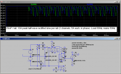
Attached picture shows:
10A pk (~7A RMS) sine load at 31Hz
15mF smoothing per rail in non-bridged, single 15mF in bridged
50V pk (~35V RMS) transformer
Upper plot is rails of non-bridged amplifier. Lower is rail-to-rail of the bridged amplifier.
Ripple valley voltage is the same.
Rail loss refers to the voltage drop in the amplifier when it clips. A bridged amplifier needs two output devices in series with the load, a great disadvantage at low voltage.
Attached picture shows:
10A pk (~7A RMS) sine load at 31Hz
15mF smoothing per rail in non-bridged, single 15mF in bridged
50V pk (~35V RMS) transformer
Upper plot is rails of non-bridged amplifier. Lower is rail-to-rail of the bridged amplifier.
Ripple valley voltage is the same.
Attachments
Last edited:
Why are you staring yourself blind at RMS voltages?
I call it concentration.
Why do they matter?
Because they determine the performance. That is what the thread is about, isn't it?
Rail loss refers to the voltage drop in the amplifier when it clips. A bridged amplifier needs two output devices in series with the load, a great disadvantage at low voltage.
A disadvantage at any voltage. The relationship remains the same regardless of absolute values.
Attached picture shows:
..absolutely nothing without the schematic it is based upon. If a schematic was attached, the picture shows double as many valleys, where the bridged amplifier would clip, while the non-bridged wouldn't. And it shows only half of the bridged amplifier's ripple voltage, because the ripple of both rails adds up in it.
Try this:
Modify your gainclone simulation so that you have two channels working from the ~+-30V supply.
What happens if you run them with the same signal in phase? What happens when one channel is run with the same but inverted signal? The ripple is lower at low load frequencies when one is inverted.
Inverted signal on one channel and halved smoothing?
If you run that simulation for yourself, you will find out that the smoothing capacitance for the inverted pair can only be reduced by ~30% for audio frequencies below 2 x fmains, but not at all for audio frequencies above 2 x fmains.
Now compare the inverted pair to a bridged amplifier and see, what it takes to make them draw the same power from the rails. Put that into relation to a single non-bridged amplifier that delivers the same power as the bridged amplifier in that example.
Where do those insights lead you? That you need 4 times the capacitance for audio above 2 x fmains, but only 2,8 times for pure subwoofer applications? And then you make the bench test and the bridged amplifier still clips earlier, because you achieved the same ripple voltage, but not the same ripple factor.
Gentlemen,
an interesting and vivid discussion is going on here...
PSRR is the ratio of the variation of amplifier output to its power supply, more explicitly, the ratio between the gain with respect to the input signal versus the gain with respect to a change in the power supply. In other words, PSRR is the reverse gain of the output ripple over the input ripple (1 / β) at a given frequency.
Thank you for your attention
Hi, Lumba Ogir,
Thanks for that hint. Does bridging two amplifiers improve PSRR compared to one non-bridged amplifer with double the rail voltage? And if so, by how much?
Thanks for that hint. Does bridging two amplifiers improve PSRR compared to one non-bridged amplifer with double the rail voltage? And if so, by how much?
pacificblue,
compared to the balanced push-pull topology, the bridge-tied load means substantially improved PSRR, eliminating the dirty grounds. It is a matter of gain not supply voltage. A dedicated topology, like the circlotron is recommended. A true balanced circuit has no ground reference in the signal path.
compared to the balanced push-pull topology, the bridge-tied load means substantially improved PSRR, eliminating the dirty grounds. It is a matter of gain not supply voltage. A dedicated topology, like the circlotron is recommended. A true balanced circuit has no ground reference in the signal path.
Where do those insights lead you? That you need 4 times the capacitance for audio above 2 x fmains, but only 2,8 times for pure subwoofer applications?
That's just trying to make it look worse. It's pointless comparing capacitances when voltage ratings are different. Do away with the ground,which isn't needed, and that's 1 or 0.7 times the capacitance. And that's still the RMS value you're looking at.
If you run that simulation for yourself, you will find out that the smoothing capacitance for the inverted pair can only be reduced by ~30% for audio frequencies below 2 x fmains, but not at all for audio frequencies above 2 x fmains.
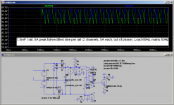
I find that it can be halved, se attached images. Half the capacitance, same ripple valley voltage, same clipping point. Why do you think you need ripple to halve towards high load frequencies? The frequency of the ripple itself is the same so PSRR isn't lower. And further, the ripple voltage still lowers toward higher frequencies, just not as much.
Attachments
I am not sure, if I get you right there. If it is only a matter of gain, it is not directly related to the topology.It is a matter of gain not supply voltage.
😕Do away with the ground,which isn't needed, and that's 1 or 0.7 times the capacitance.
What else? Do your amplifiers only reproduce one frequency, where the amplitude peaks always happen to be in phase with the ripple valleys? When you play music, the amplitude peaks will equally often happen at any point of time. Sometimes just, where a ripple valley is, sometimes at a ripple peak, i. e. at a higher voltage. The average clipping will coincide with the rms ripple voltage.And that's still the RMS value you're looking at.
And there are more reasons, why I am looking at the rms value. It is taught that way at German universities. It is documented in all textbooks I know that deal with that topic. It coincides with my experience.
You haved posted several pictures that all show the same. You see that the valleys reach the same level, I see that the rms value is different. You can keep on posting those pictures as often as you like, and my opinion will not change. I showed you in post #47 that the bridged amplifier clips earlier, in spite of the same ripple voltage per rail.I find that it can be halved, se attached images.
Why do you think you need ripple to halve towards high load frequencies?
The bridged amplifier draws current from both rails at the same time, therefore the ripple voltages add up. The non-bridged ampplifier only draws from one rail at a time, therefore the ripple voltage of that rail only is effective.
- Status
- Not open for further replies.
- Home
- Amplifiers
- Solid State
- PSU capacitor design