For £2 each they will be fake.

Not according to my LC meter.
Depends on who you buy them from.
Not according to my LC meter.
Depends on who you buy them from.
Who are you buying them from?
Indigenous Chinese brands tend not to get faked, on Taobao a Sancon 10,000uF/63V shows up under $2 so this suggests its possible to get a genuine cap at that price. Caps designed especially for audio tend to get faked more because the margins are higher.
https://item.taobao.com/item.htm?spm=a230r.1.14.212.hK0GfY&id=39111314806&ns=1&abbucket=13#detail
https://item.taobao.com/item.htm?spm=a230r.1.14.212.hK0GfY&id=39111314806&ns=1&abbucket=13#detail
Indigenous Chinese brands tend not to get faked, on Taobao a Sancon 10,000uF/63V shows up under $2 so this suggests its possible to get a genuine cap at that price. Caps designed especially for audio tend to get faked more because the margins are higher.
https://item.taobao.com/item.htm?spm=a230r.1.14.212.hK0GfY&id=39111314806&ns=1&abbucket=13#detail
Just found this: $4.00 including shipping.
63V 10000UF 30*50mm Aluminum electrolytic capacitor (1Pcs)-in Capacitors from Electronic Components & Supplies on Aliexpress.com | Alibaba Group
Now, the cheapest 10mF/63V on digikey.com is $4.63
from Cornell-Dubilier-Electronics, supposedly made in USA.
I'm using CDE caps in some of my projects, so far so good.
SLPX103M063E9P3 Cornell Dubilier Electronics (CDE) | Capacitors | DigiKey
That Aliexpress link looks to me a concern - there are two pics and the second one (black) is a no-name brand. The description says the cap's black so could easily be a bait-and-switch.
That Aliexpress link looks to me a concern - there are two pics and the second one (black) is a no-name brand. The description says the cap's black so could easily be a bait-and-switch.
Yeah, for couple of dollars I wouldn't bother with taking extra risk.
CDE caps are fine.
Also Panasonic caps tend be 'on sale' from time to time,
when mouser sells 'end-of-the-line' leftovers.
Looking for caps on Aliexpress, it looks to be rather a wilderness compared to Taobao, very little choice and 'Rukycon' doesn't inspire too much confidence (although I've not tried them myself, they might be fine). I prefer Chinese brands which don't blatantly copy Japanese cap brands.
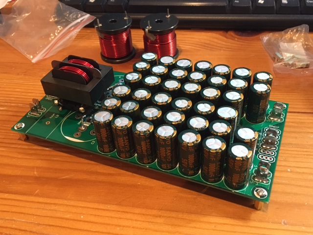
I recently got qnty 40 x 1000uF 50v caps that appear to be genuine Sanyo's. They measure well and add up to 20,000uF for $4.18 per rail. ESR measured at 0.06ohm ea so when used in a cap array makes for a pretty low ESR cap (0.060/20=3milliohm).
10pcs 50V1000UF High Frequency Low Resistance Filter Plug Electrolytic Capacitor 50V 1000UF Volume 13X20-in Capacitors from Electronic Components & Supplies on Aliexpress.com | Alibaba Group
10pcs 50V1000UF High Frequency Low Resistance Filter Plug Electrolytic Capacitor 50V 1000UF Volume 13X20-in Capacitors from Electronic Components & Supplies on Aliexpress.com | Alibaba Group
I recently got qnty 40 x 1000uF 50v caps that appear to be genuine Sanyo's.
Based on the quality of the printing on the sleeves in the pic at that link, I'd say almost certainly not genuine. Not to say they can't work fine though - I have some impressive measuring 'Shanyo' caps, very low ESR. Watch the supply voltage - if you've not powered those up yet, I'd do it gently on a variac and check the leakage current as you do this. Many of my fake Sanyos exploded when exposed to their rated voltage, worked fine at around 60% of marked voltage though.
I have been using them at 35v so probably OK - the price does seem too good to be true. However, they are quite functional.
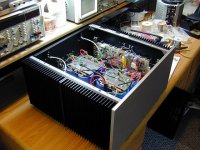
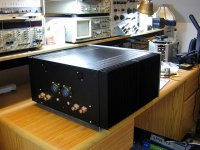
One of my babies.
Dual Mono with two external transformers. Each channel has 4 x 22,000uF/100V CDE caps.
Very nice! I see you are using mil-spec 4-contact Amphenols on the back for the DC supply lines. I assume you are using the scheme shown earlier: +ve, -ve, DC 0v, and earth gnd?
I have been using them at 35v so probably OK - the price does seem too good to be true.
Another give-away that they're most likely fake is the case size for the capacity/voltage. Samyoung (best bang for the buck I reckon) 35V/1000uF is taller and same diameter - 50pcs Korea SAMYOUNG 35V1000UF 35v LXV 13X25mm Promotion Kit new Aluminum Electrolytic Capacitor freeshipping computer Odroid-in Capacitors from Electronic Components & Supplies on Aliexpress.com | Alibaba Group
Very nice! I see you are using mil-spec 4-contact Amphenols on the back for the DC supply lines. I assume you are using the scheme shown earlier: +ve, -ve, DC 0v, and earth gnd?
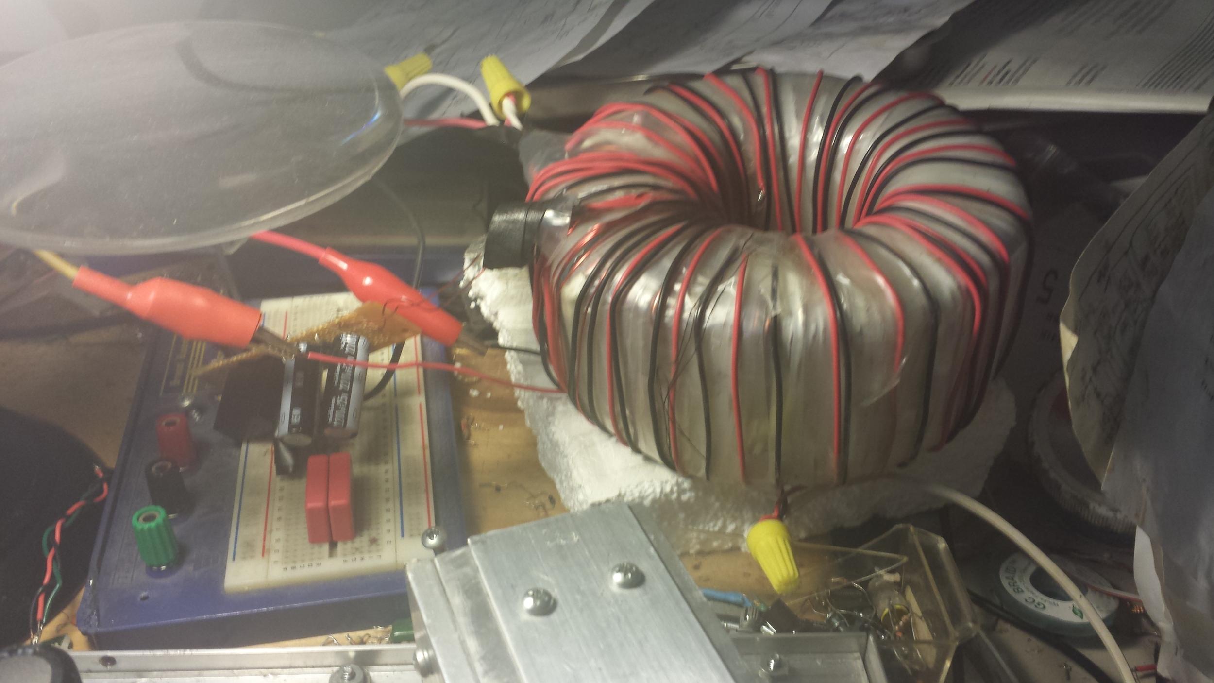
I think these are for AC. Transformers are external; rectifiers and caps are internal.
This is the way to import the interference effect of half wave pulses into your amplifier.The way I do it is to house the transformer externally and run a cord to the amp chassis which has the rectifier and filter caps inside. This way, my filter caps are just beside the amp modules. No problems, even with cord of 2 meters.
Instead transform, rectify and smooth at the PSU.
Run a twisted triplet, with +ve, Zero Volts and -ve all in the power cable, to the amplifier.
At the amplifier you MUST fit local supply rail decoupling. As a minimum this will consist of very low inductance ceramic X7R capacitors on the output devices and >=100uF of electrolytic capacitors on the amp PCB.
If there is a lot of impedance between the PSU and the amplifier (the power cabling) you may consider that the electrolytic part of the local supply rail decoupling could be increased upto as high as 2200uF for each output device.
Last edited:
Very nice! I see you are using mil-spec 4-contact Amphenols on the back for the DC supply lines. I assume you are using the scheme shown earlier: +ve, -ve, DC 0v, and earth gnd?
Thanks.
I'm actually running AC from the transformer secondaries to the amp. The Bridge rectifiers and Filter caps are inside the amp box. Basically, I'm just stepping down the Mains voltage to whatever the amp needs.
This way, I don't have the problems associated with long DC supply lines.
This is the way to import the interference effect of half wave pulses into your amplifier.
As I said before, the bridge rectifier is inside the amp chassis.
If I were to have the entire psu externally (transformer, rectifier, filter caps), I will have to resolve the issues of running long DC supply lines.
With only the power transformer housed separately, it's a simpler and cheaper solution. It's not perfect, but good enough for me.
I find it does not hurt at all to build the entire PSU right on to the amplifier PC board. Layout is important of course as it always is. Why have DC wires that are just going to be a hassle? In this amp HERE, the only power connection is the center tapped secondary of the power transformer (THIS transformer😀), and also there is a small current voltage doubler circuit included (AC required🙄 ). Very solid amp, no problem with 100Wave @4R, plus surround speakers.........BTW a new advanced model coming soon. 
Read the whole Thread and get a feeling for the Safety issues.
Then you can make up your mind on what you decide is necessary for home insurance and friends/children in the vicinity.
One more idea - while I'm at it, I could have this PSU to give 2 different
voltages, say +/- 76V and +/- 64V.
Say I use toroidal transformer able to deliver +/- 76V DC,
how about adding a chain of diodes (10A) to have 2nd set of outputs for +/-64V DC? I guess this shouldn't mess up anything.
Any opinions? Any decoupling needed AFTER diodes?
- Status
- Not open for further replies.
- Home
- Amplifiers
- Solid State
- PSU and amp in separate encolsures