Have anyone tried to build a PSU (transformer, rectifier, capacitors)
in a separate box, and have it connected to the amp by 1 meter cable?
Any issues with hum/grounding?
I would like to re-use one PSU (say +/64V) with multiple amps,
rather than building ($$) new PSU in every amp I'm testing in my
living room. Also, amp case can be thinner/smaller in this case.
in a separate box, and have it connected to the amp by 1 meter cable?
Any issues with hum/grounding?
I would like to re-use one PSU (say +/64V) with multiple amps,
rather than building ($$) new PSU in every amp I'm testing in my
living room. Also, amp case can be thinner/smaller in this case.
I want to do something similar when I make a box for my amps. Right now they all get tested in a sheet of plywood and the power supply transformer and PSU rectifier and caps are shared by putting various amps under test in and out. Seeing this - it would seem that a separate PSU box maybe adjacent to main amp and connected by large gauge wires with crimped eyelet connectors and screw terminal blocks makes sense. You have to make sure to use star ground topology to avoid ground loops. The longer run of 1m is probably not an issue with noise as you would be running high current low impedance DC lines.
I have been able to use a common center tap for both monoblock channels with separate rectifiers and caps but have heard that ground loop issues could arise in such a case. Dual transformers or transformers with dual center tap outputs would avoid ground loops to start with.
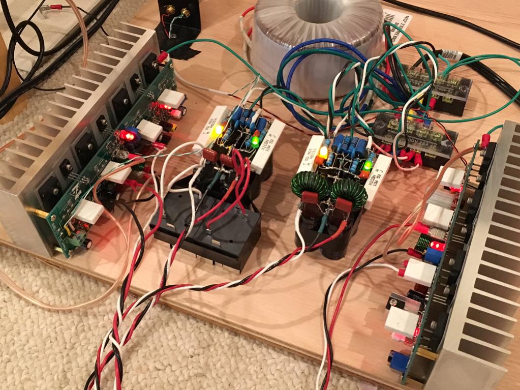
Here is my current setup that will be transferred to a case. Probably separate PSU case...
I have been able to use a common center tap for both monoblock channels with separate rectifiers and caps but have heard that ground loop issues could arise in such a case. Dual transformers or transformers with dual center tap outputs would avoid ground loops to start with.
Here is my current setup that will be transferred to a case. Probably separate PSU case...
A non-issue I would say. Not much different from using a regular lab PSU, which is commonly used for hobby projects such as this. I used one when I built a Circlophone.
http://www.diyaudio.com/forums/power-supplies/115698-understanding-star-grounding-3.html#post1532442
There may be a later post, but this gives some idea on where this Thread was going.
Worth reading the whole Thread from post1.
There may be a later post, but this gives some idea on where this Thread was going.
Worth reading the whole Thread from post1.
http://www.diyaudio.com/forums/power-supplies/115698-understanding-star-grounding-3.html#post1532442
There may be a later post, but this gives some idea on where this Thread was going.
Worth reading the whole Thread from post1.
Thanks Andrew.
"dual mono grounding" as mentioned in that thread - that's what I need (kind of).
Interesting thing: chassis ground wire is routed separately
from PSU 0V wire.
So 4 wires in total between PSU and amp (plus remote start, etc.. signals).
What can go wrong if there is only one 'ground' wire?
I know with AC mains it's different story, but with DC? These two are surely connected together in the PSU.
Read the whole Thread and get a feeling for the Safety issues.
Then you can make up your mind on what you decide is necessary for home insurance and friends/children in the vicinity.
Then you can make up your mind on what you decide is necessary for home insurance and friends/children in the vicinity.
I'm reading.
Read the whole Thread and get a feeling for the Safety issues.
Then you can make up your mind on what you decide is necessary for home insurance and friends/children in the vicinity.
So this is the recommended topology? What about when only one set of shared center tap transformer is used but two separate rectifiers and filter banks? Or is this diagram already accounting for that?
Have anyone tried to build a PSU (transformer, rectifier, capacitors)
in a separate box, and have it connected to the amp by 1 meter cable?
Any issues with hum/grounding?
A classAB amplifier has half-wave rectified versions of the output current flowing on its supplies. It doesn't make sense to increase the loop area and impedance of the wiring those currents are flowing through.
I'd suggest series inductors between the boxes and having substantial capacitance local to the amp. In other words, configure your supply as CLC with the first C in the transformer box and the second one as close to the amp as you can manage.
The long power leads have inductance and resistance and you might get some instability in the amp.
How to prevent/minimize this?The long power leads have inductance and resistance and you might get some instability in the amp.
Speaker wires are long. Transformer wiring is long too, so these kind of things must be already happening to some degree.
Since the current flows in a loooong loop from secondaries in the transformer all the way to the speaker, I hope one extra meter of wire
wont spoil it too much....
A classAB amplifier has half-wave rectified versions of the output current flowing on its supplies. It doesn't make sense to increase the loop area and impedance of the wiring those currents are flowing through.
I'd suggest series inductors between the boxes and having substantial capacitance local to the amp. In other words, configure your supply as CLC with the first C in the transformer box and the second one as close to the amp as you can manage.
Understood. What kind of inductors? Any specific pointers?
How to prevent/minimize this?
Speaker wires are long. Transformer wiring is long too, so these kind of things must be already happening to some degree.
Since the current flows in a loooong loop from secondaries in the transformer all the way to the speaker, I hope one extra meter of wire
wont spoil it too much....
I would decouple the amplifier module well.
Maybe even add some 470uf electrolytics across the power supply.
The main worry is the output transistors not being decoupled well enough and starting to oscillate.
Also any extra hum or noise on the power supply will get into the front end if that isn't decoupled well.
Class AB shouldn't be too bad.
I have had problems with class d amps starting to reset if the smoothing caps aren't close to output mosfets.
Have anyone tried to build a PSU (transformer, rectifier, capacitors) in a separate box, and have it connected to the amp by 1 meter cable?
The way I do it is to house the transformer externally and run a cord to the amp chassis which has the rectifier and filter caps inside. This way, my filter caps are just beside the amp modules. No problems, even with cord of 2 meters.
I would decouple the amplifier module well.
Maybe even add some 470uf electrolytics across the power supply.
The main worry is the output transistors not being decoupled well enough and starting to oscillate.
Also any extra hum or noise on the power supply will get into the front end if that isn't decoupled well.
Class AB shouldn't be too bad.
I have had problems with class d amps starting to reset if the smoothing caps aren't close to output mosfets.
For this specific amp I'm planning to use this solution for, there are
already 2 x 2700uF on each board. Well, will test it, and we will see...
Understood. What kind of inductors? Any specific pointers?
It rather depends on how much DIYing you'd like and how much you want to veer towards an 'off the shelf' solution. Myself I tend towards the former - I buy cores and wind them myself. It also depends how much you'd like to spend.
If you're not afraid to splash the cash, then high flux toroidal cores would be the way to go : CWS ByteMark, largest supplier of toroids, ferrite cores, iron powder cores, MPP cores and RF cores
If you look at how Nagra's designed the power supply for their newest poweramp, it looks like they're using a similar approach although all within one box. They have two boards - one for the first cap and inductors adjacent to the trafo, the second bank of caps is adjacent to the amp and has very substantial bus-bars between caps and semiconductors for the lowest possible impedance.
http://www.nagraaudio.com/wp-content/gallery/hd-amp/HD_AMP_inside.jpg
I have designed quite a few amps so I have old amplifier case with a transformer and smoothing capacitors in it.
On flying lead with croc clips (12 inches long) I connect to any amplifier module I am working on.
Not seen any problems with class AB as I decouple them well anyway.
However, a class d amp didn't like it at all.
I had to redesign the pcb with smoothing caps close to output mosfets.
On flying lead with croc clips (12 inches long) I connect to any amplifier module I am working on.
Not seen any problems with class AB as I decouple them well anyway.
However, a class d amp didn't like it at all.
I had to redesign the pcb with smoothing caps close to output mosfets.
The way I do it is to house the transformer externally and run a cord to the amp chassis which has the rectifier and filter caps inside. This way, my filter caps are just beside the amp modules. No problems, even with cord of 2 meters.
I was thinking about going this route - AC wiring in the house spans 100s of meters after all,
but caps are also expensive - usually more costly than the transformer itself. I think I'll try CLC solution mentioned earlier - some caps in the PSU enclosure, and extra caps in the amp enclosure.
Plus inductors.
but caps are also expensive - usually more costly than the transformer itself. I think I'll try CLC solution mentioned earlier - some caps in the PSU enclosure, and extra caps in the amp enclosure.
I find for something like a 150WRMS amp that 10,000uf per rail is good enough. I don't subscribe to the massive smoothing capacitor camp and never had any problems.
You can get 10,000uf 63v from China for £2 each.
You can get 10,000uf 63v from China for £2 each.
For £2 each they will be fake.

- Status
- Not open for further replies.
- Home
- Amplifiers
- Solid State
- PSU and amp in separate encolsures